BM料架治具使用手册.pdf - 第49页
OK OK: T wo marks do not move and appear to be overlapped. Camera view select lever Y direction (Feed direction) X direction (Width direction) NG: T wo marks appear to be misaligned after switching the lever. After switc…
4.1 Adjusting Wheel Position
Feeder Inspection Unit
4.1−5
DX1OEC−31−240−B0
Checking the Wheel Position Hole (or Vacuum Position Hole)
1. Set the camera view select lever to the R side.
2. Adjust the focus displayed on the monitor using the adjust knob (Z).
3. Using the knobs (X, Y and Z), adjust the camera position so that the wheel position hole or vacuum
position hole may be aligned with the center of the cross hairs, while observing the X/Y graduation
plates and the monitor.
4. Then, tighten the lock knobs (X, Y and Z) to secure the camera.
=HINT=
To ensure measurement accuracy, tighten the lock knobs to secure the camera in position.
8
V
Lock knob (Y)
Lock knob (X)
Graduation
plate (X)
Graduation
plate (Y)
Adjust knob (X)
X slider
Lock
knob (Z)
Adjust
knob (Z)
Z slider
Y slider
Adjust
knob (Y)
Align the edge of the X slider with
the predetermined graduation.
Align the edge of
the Y slider with
the predetermined
graduation.
V
8
12
16
24
32
44
56
72
MOTOR
V
0603W
AIR
W
=HINT=
How to utilize the graduation plate
• The marks on the graduation plate is used for rough positioning with respect to the wheel position
hole of the gauge jig.
• Align the edge of the X/Y sliders and graduation plate according to the feeder type and width. This
enables you to find the target wheel holes easily.
Then, make fine−adjustment of the camera position for the wheel position hole of the gauge jig.
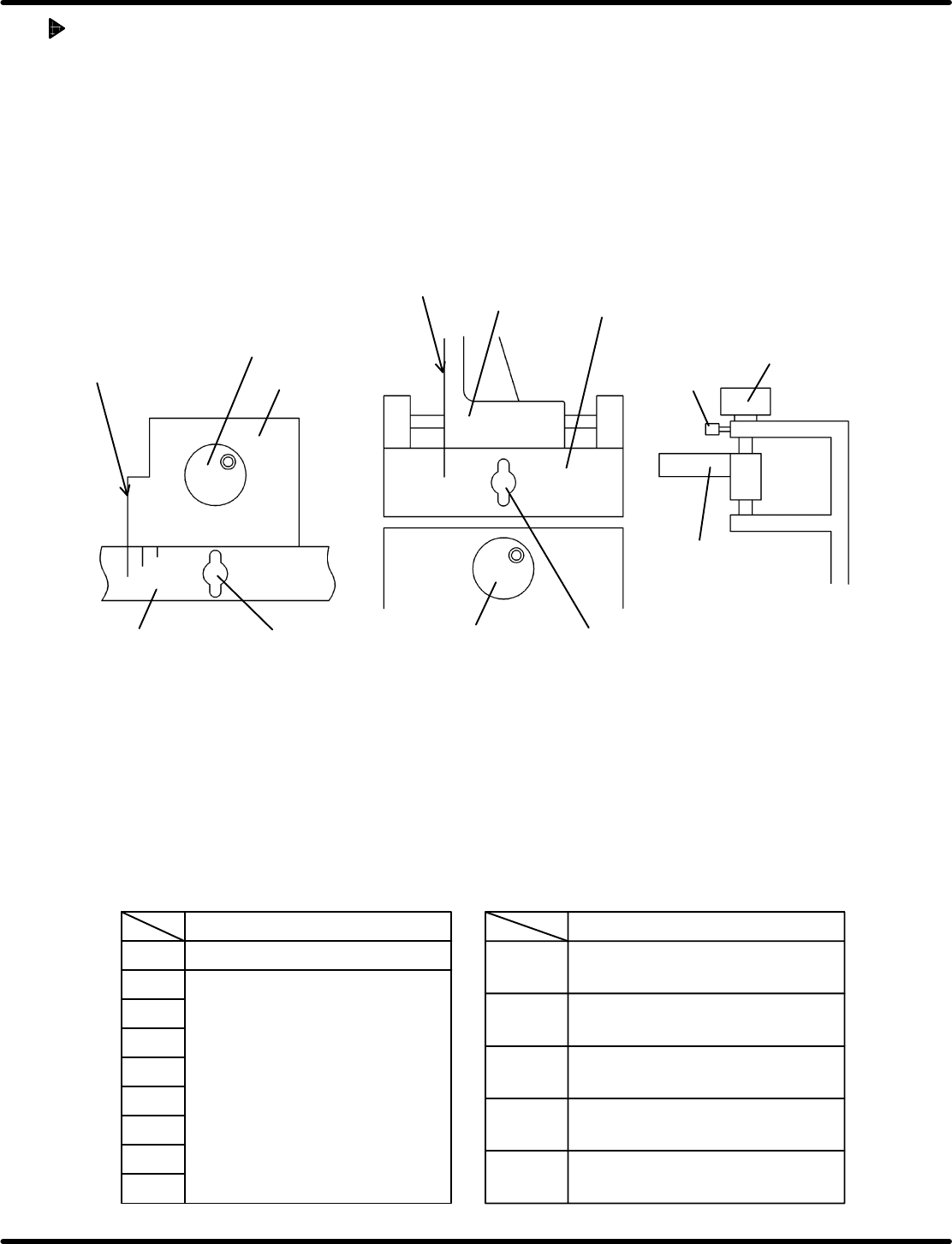
• The tables below show how the positions on the X/Y graduations plates correspond to the feeder
type.
Pickup position
X slider position Y slider position
Motorized feeder
Pickup position
Wheel positions for 8 − 72 mm
Pneumatic double feeder
(For 0603)
Pneumatic feeder
Pneumatic double feeder
(Other than 0603)
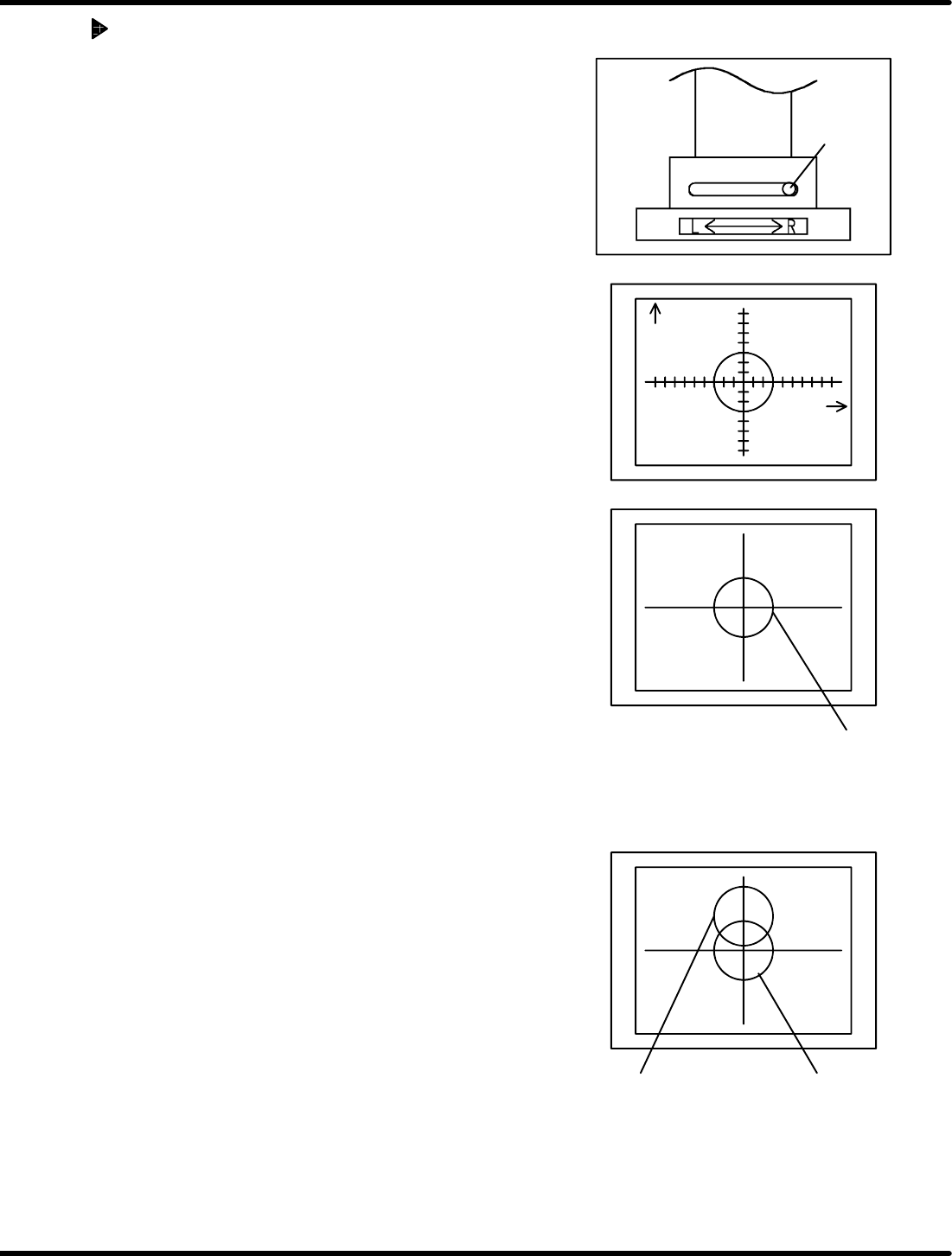
OK
OK: Two marks do not move and appear
to be overlapped.
Camera
view select
lever
Y direction
(Feed direction)
X direction
(Width
direction)
NG: Two marks appear to be misaligned
after switching the lever.
After switching
camera view
select lever
Before switching
camera view
select lever
Feeder Inspection Unit
4.1 Adjusting Wheel Position
4.1−6
DX1OEC−31−240−B0
Checking the Camera Position
1. Attach the gauge jig to the clamp stand.
2. Set the camera view select lever to the R side.
3. Align the gauge hole (V
R
) with the center of the monitor
by adjusting the knobs (X, Y and Z).
=HINT=
The Z adjustment knob is used for camera focusing.
4. Positioning is correct when the gauge hole (V
L
) appears
at the center of the monitor when the camera view select
lever is set to the L side.
5. If the camera position is not correct, re−adjustment is
necessary. (Refer to ‘5.1.1 Adjusting the Camera
Position’.)
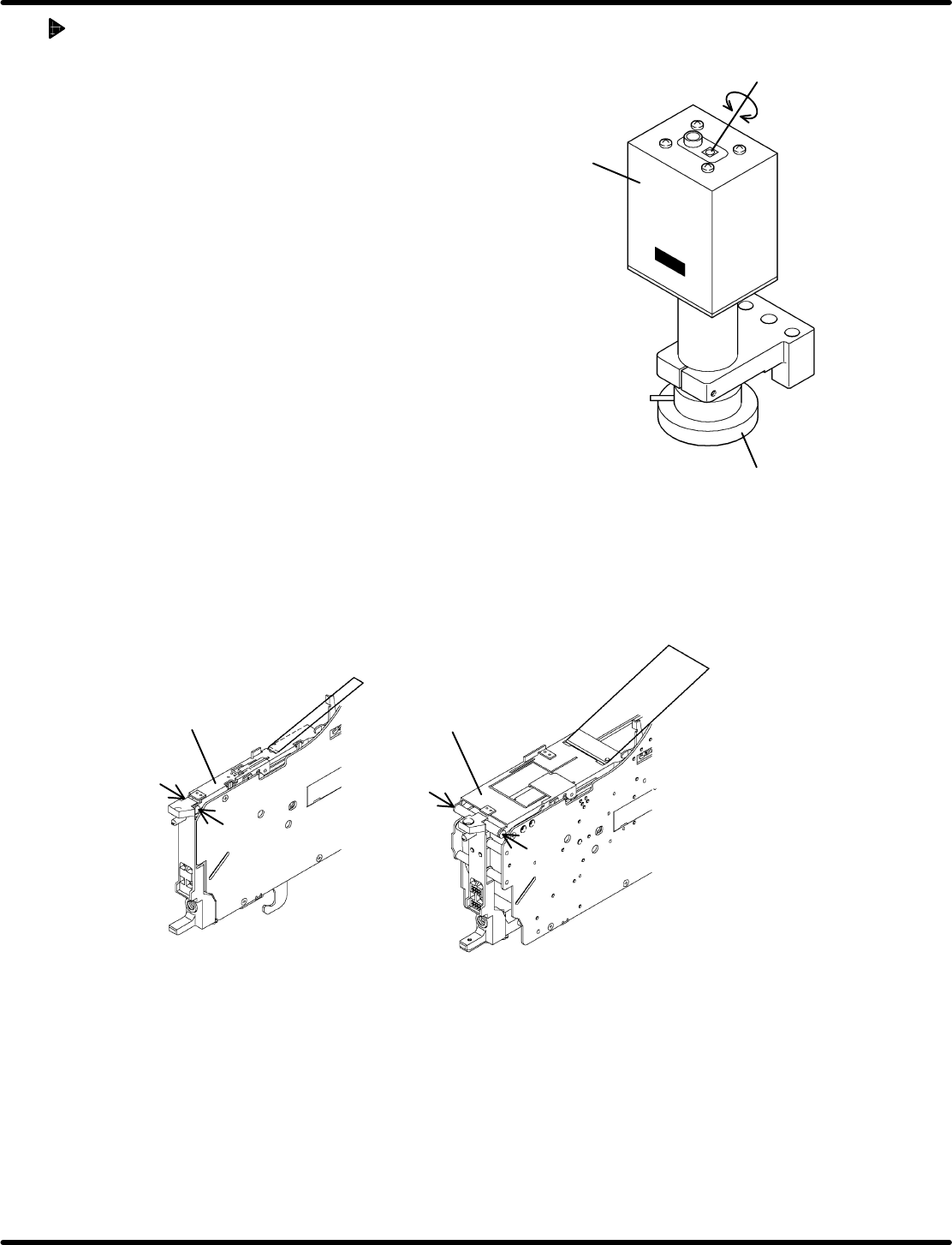
Camera
LED
Varistor for adjusting light
intensity
4.1 Adjusting Wheel Position
Feeder Inspection Unit
4.1−7
DX1OEC−31−240−B0
Adjusting LED
• If the holes in the gauge or object to be checked cannot
be seen clearly on the monitor, adjust the brightness of
the LED of the camera.
• Adjust the brightnes s by turning the varis tor for
adjusting light intensity.
• Use a Phillips screwdriver when turning the varistor for
adjusting light intensity.
4.1.4 Removing Tape Retainer
Because of the structure of the feeder, it may be necessary to remove the tape retainer or tape guide
when checking the wheel position. Observe the below procedure, if applicable, to remove them before
checking.
Regarding the following feeders, the tape guide need be removed.
• Motorized feeders (12 to 72 mm tape)
Set screw
Set screw
Set screw
Set screw
12 − 24 mm 32 − 72 mm
Tape guide
Tape guide
Removing the set screws permits you to detach the tape guide from the feeder.
=REFERENCE=
After inspecting or checking, reattach the tape guide reversing the removal procedure.
Concerning the following feeders, the feed wheel can be seen with the tape guide loaded normally.
• Pneumatic feeder
• Pneumatic double feeder
Remove the taping component and hook the tape guide.