BM料架治具使用手册.pdf - 第45页
Feeder Inspection Unit 4.1 Adjusting Wheel Position 4.1−2 DX1OEC−31−240−B0 • 32 mm or wider tape feeders have a feed wheel on both sides. So the feed wheel on the drive side (far side as seen from the control panel) only…

4.1 Adjusting Wheel Position
Feeder Inspection Unit
4.1−1
DX1OEC−31−240−B0
4.1 Adjusting Wheel Position
DX1OEC−31−240−B0
Sentence No.
The feeder adjust unit enables the following inspection and check with the built−in camera.
• Inspecting wheel positions (tape feed direction and tape width direction)
• Checking component status at the pickup position
4.1.1 Inspection Procedure
Perform the following procedure when checking the wheel position of the tape feeders.
Preparations for Adjust Unit
=REFERENCE=
Refer to ‘4.1.3’.
1. Attach the master jig.
2. Turn power ON.
3. Supply air.
4. Check the camera position.
Preparations for Tape Feeder
=REFERENCE=
Refer to ‘4.1.4’.
1. For motorized feeder, detach the tape holder.
2. Remove taping components from the tape feeder.
Setting Camera Position
1. Attach the master jig.
2. Move the camera to a wheel position hole in the plate of the master jig and secure it.
(At this time, choose a wheel position hole conforming to the type of the tape feeder and
specifications.)
Inspecting Wheel Position
1. Attach the tape feeder to be checked.
=REFERENCE=
Refer to ‘4.1.5’ and ‘4.1.6’.
2. Check if the wheel position is within the range of standard value.
(The standard value varies with the types of tape feeder or specifications.)
3. When inspecting tape feeders with different types or out of specifications, reset the camera position.
(Repeat steps from ‘" Preparations for Tape Feeder’.)
Adjusting Wheel Position
=REFERENCE=
Refer to ‘4.1.5’ and ‘4.1.6’.
1. If the wheel position is outside the range of standard value, adjust the wheel position.
=HINT=
• When checking the wheel position of the tape feeder, the wheel cannot be seen unless the tape
guide is removed depending on the model.
• The wheel position of 32 mm paper feeder cannot be checked. Operation check can only be made.

Feeder Inspection Unit
4.1 Adjusting Wheel Position
4.1−2
DX1OEC−31−240−B0
• 32 mm or wider tape feeders have a feed wheel on both sides. So the feed wheel on the drive side
(far side as seen from the control panel) only will be inspected.
4.1.2 Checking Component Status at the Pickup Position
(Reference)
Follow the procedure below to check the status of components when feeding the tape feeder.
Preparations for Adjust Unit
=REFERENCE=
Refer to ‘4.1.3’.
1. Attach the master jig.
2. Turn power ON.
3. Supply air.
4. Check the camera position.
Preparations for Tape Feeder
1. Set taping components to the tape feeder.
Setting Camera Position
1. Attach the master jig.
2. Move the camera to a wheel position hole in the plate of the master jig and secure it.
Checking Component Status at the Pickup Position
=REFERENCE=
Refer to ‘4.1.7’.
1. Attach the tape feeder concerned.
2. Feed the tape feeder and check for components.
=HINT=
When checking the pneumatic double feeder on the L side, set the camera view select lever to the
L side.
3. When checking other tape feeder, keep the camera position as it is and replace the feeder only.
=HINT=
• Dimensions of taping components are limited. If smaller than the view of camera (2 mm by 2.7 mm),
checking can be made.
• Taping components can only be used with a small reel (reel dia.: φ178 mm).
• Consider the component pickup position check to be for reference purpose only. Therefore, adjust
the feed position using the feed wheel.
• When directly checking components at the pickup position, some cannot be seen clearly depending
on the types of paper tape or embossed tape.
Stopper
Air conductor
4.1 Adjusting Wheel Position
Feeder Inspection Unit
4.1−3
DX1OEC−31−240−B0
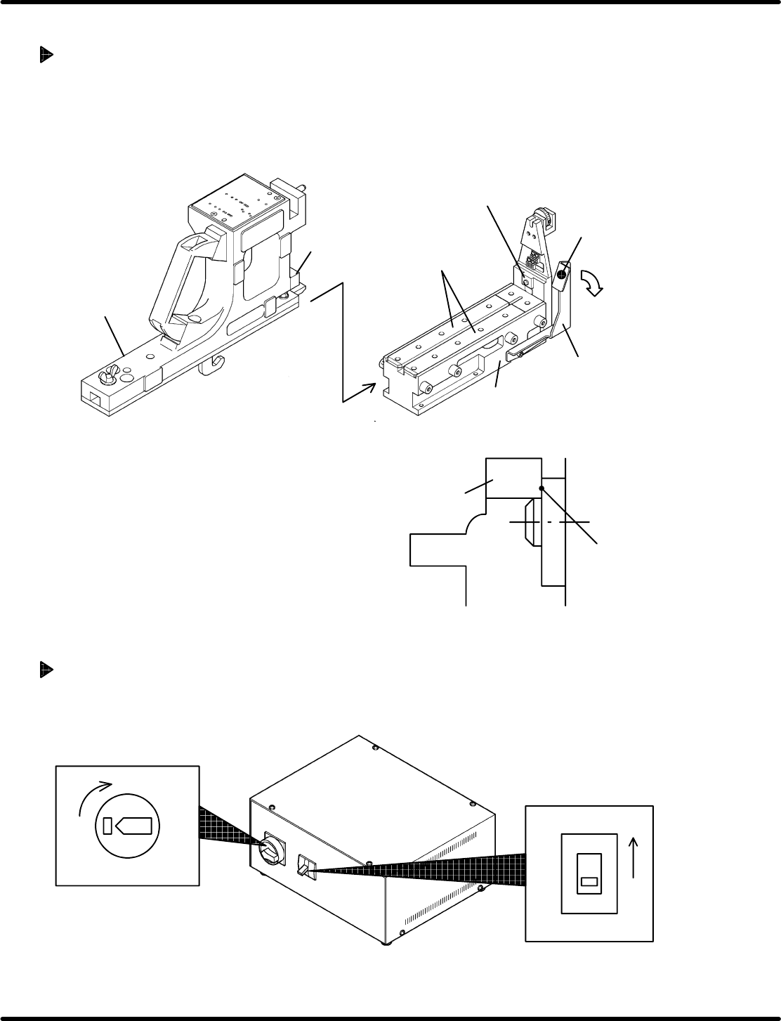
4.1.3 Preparations for Inspection
Attaching the Gauge Jig
1. Attach the gauge jig along the guides of the clamp stand.
=HINT=
When attaching/detaching the gauge jig and feeder, pushing the clamp reset lever enables the
clamp to be released.
This allows the gauge jig and feeder to be attached/detached easily.
Stopper
Gauge jig
Clamp reset lever
Push
Guide
Air conductor
Clamp stand
2. Ensure that the stopper of the gauge jig and air
conductor of the clamp stand have been fitted
properly without any gap.
=REMARKS=
• To ensure c lamping, av oid pus hing the
clamp reset lever when fitting the stopper
to the air conductor.
• Check if the fitting is proper for accurate
inspection. If there is a gap, the gauge jig
can be displaced.
Turning Power ON
1. Turn ON the breaker switch.
2. Turn ON the main switch.
Breaker switch
ON
ONOFF
Main switch