BM料架治具使用手册.pdf - 第40页
3.2 Connecting Method Feeder Inspection Unit 3.2−3 DX1OEC−1 1−080−A0 Detailed Drawing of Air Connection Camera (1) Insert the air tube while pushing upward. (2) After connecting the air tube, secure it with a clip. V alv…
Feeder Inspection Unit
3.2 Connecting Method
3.2−2
DX1OEC−11−080−A0
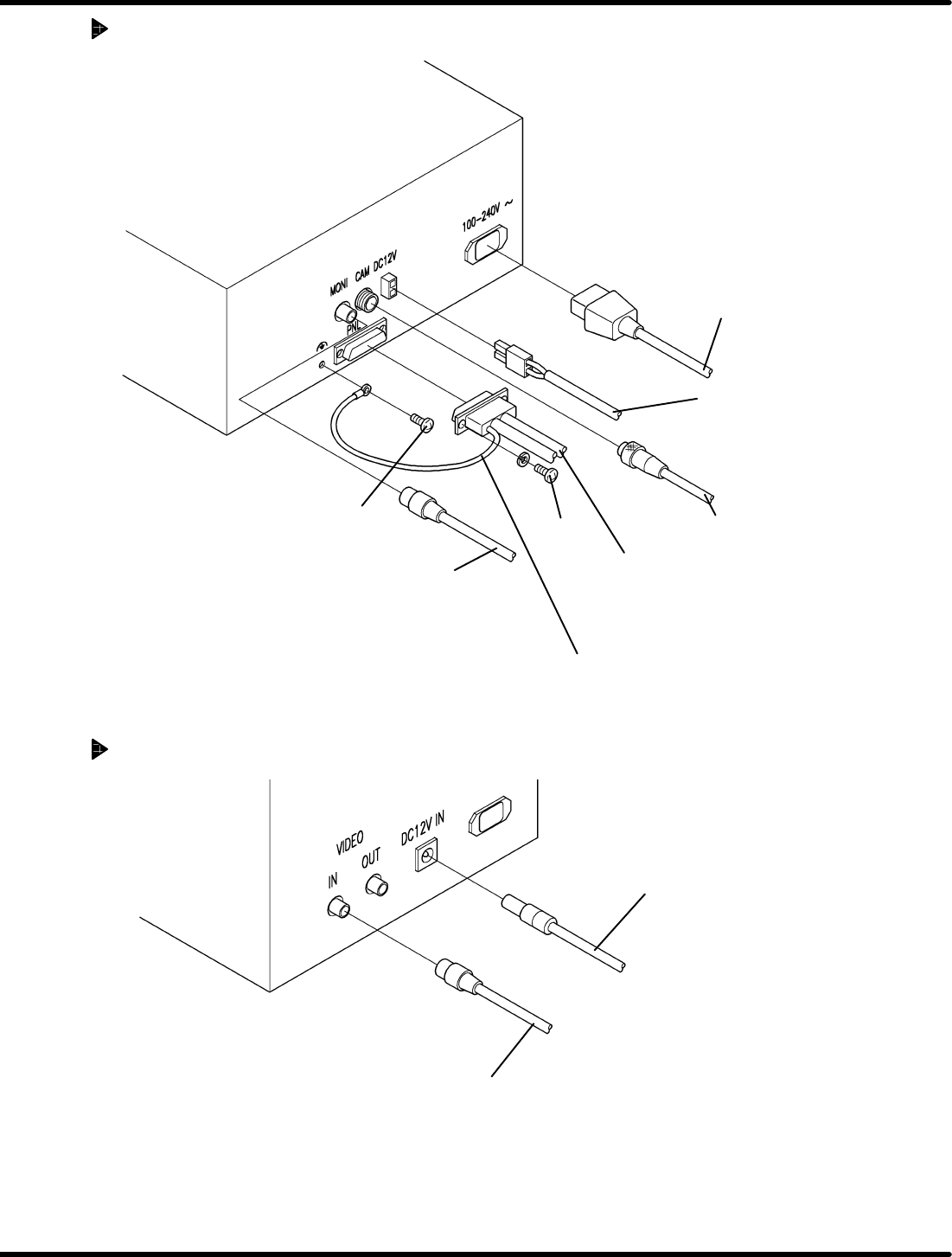
Detailed Drawing of Power Box Connection
PNL cable
(Power box − Adjust unit)
• Tighten screws on both ends of
the connector.
Ground cable
• Be sure to connect the ground cable.
Power cable for
power box
Set screw
Screw
Camera cable
(Power box − Camera)
Monitor signal cable
(Power box − Monitor)
Monitor power cable
(Option)
(Power box − Monitor)
Detailed Drawing of Monitor (Option) Connection
Monitor signal cable
(Power box − Monitor)
Monitor power cable
(Option)
(Power box − Monitor)
3.2 Connecting Method
Feeder Inspection Unit
3.2−3
DX1OEC−11−080−A0
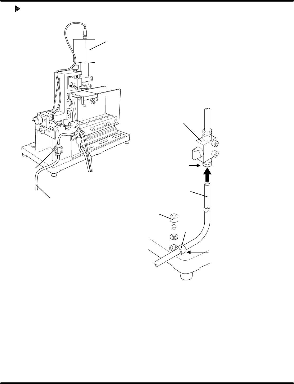
Detailed Drawing of Air Connection
Camera
(1)
Insert the air tube while
pushing upward.
(2)
After connecting the
air tube, secure it
with a clip.
Valve
Air tube (φ6)
Screw
Clip
Valve
Air tube (φ6)

Feeder Inspection Unit
3.2 Connecting Method
3.2−4
DX1OEC−11−080−A0
= MEMO =