BM料架治具使用手册.pdf - 第59页
Feeder Inspection Unit 4.1 Adjusting Wheel Position 4.1−16 DX1OEC−31−240−B0 = MEMO =
Pickup position V
R
Set the view select
lever to the R side.
4.1 Adjusting Wheel Position
Feeder Inspection Unit
4.1−15
DX1OEC−31−240−B0
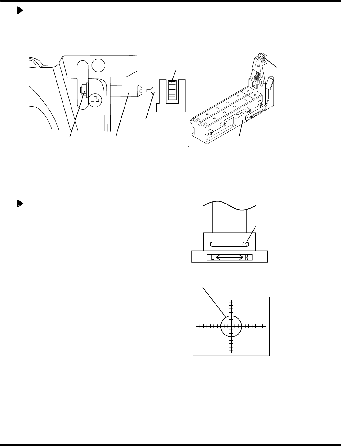
Adjustment Procedures
1. Secure the positioning pin to the clamp stand with an attached screwdriver.
2. While securing the positioning pin with the screwdriver, loosen the nut using a wrench.
3. Since the positioning pin is decentered, rotate it with a screwdriver to adjust so that the feed wheel
tooth may fall within the standard value range of the stop position. Then secure the positioning pin.
Positioning pin
Nut
Screwdriver
Rotating knob
Clamp stand
Screwdriver
4.1.7 Checking Component Status at the Pickup Position
If the taping component is smaller than the camera
view (2 x 2.7 mm), the status of the fed component can
be checked at the pickup position.
Procedure
1. Attach the gauge jig to the clamp stand.
2. Set the camera view select lever to the R side.
3. Move the camera according to the V
R
of the gauge
jig and lock in place.
4. Attach a tape feeder containing the taping
components to the clamp stand.
This completes the preparation.
(For steps 1. through 4. , refer to ‘4.1.2’ and ‘4.1.3
Preparations for Inspection’.)
5. Set the panel switch according to the model of the
tape feeder to be checked.
Pressing “AUTO” allows you to check the status of
the fed taping components during feeding.
(For details on handling the panel switches, refer to
‘4.2 Tape Feeder Operation Check’.)

Feeder Inspection Unit
4.1 Adjusting Wheel Position
4.1−16
DX1OEC−31−240−B0
= MEMO =
4.2 Tape Feeder Operation Check
Feeder Inspection Unit
4.2−1
DX1OEC−31−250−A0
4.2 Tape Feeder Operation Check
DX1OEC−31−250−A0
Sentence No.
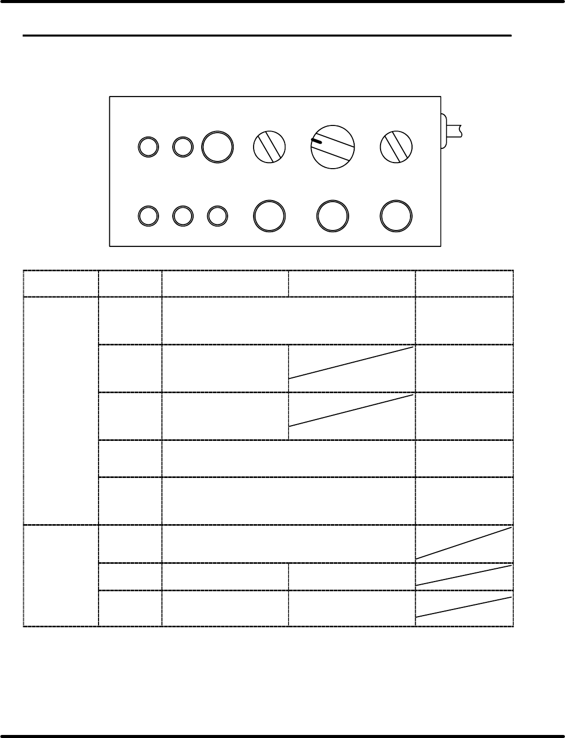
4.2.1 Control Panel Layout and Function
Here following describes the names and function of the switches on the control panel.
TAPE STATUS
LED ON
1
CASSETTE TYPE
2OP 2
FEED
TIMES
30
PEEL
SELECT
1
41
FEED
OK
ERROR TIME UP
AUTO FEED PEEL
Applicable
feeder
Pneumatic feeder
(Double feeder included)
Motorized feeder Criteria
Indicator lamps FEED OK Lights up when operation is normally finished after <AUTO>
is pressed.
When feeder
operation finishes
normally, the lamp will
come on.
ERROR Lights up if no feed operation
is executed within the
prescribed time after
“AUTO” is pressed.
Feeder operation
error
TIME UP Lights up if the cylinder
operation is not detected
within the prescribed time
after “AUTO” is pressed.
Feeder operation
error
TAPE Lights up when the tape detection sensor is turned ON.
(Available for the feeders with tape end detection function.)
Used when checking
sensor for proper
operation.
STATUS Lights up when the cylinder is at the forward limit or reverse
limit with the sensor ON.
(Checks the forward and reverse sensors of the cylinder for
proper operation.)
Check the cylinder
position and sensor
status.
Setting switches CASSETTE
TYPE
Usually, set to “1”.
When using a double feeder, set this switch to “2” to activate
the L side and set it to “1” to activate the R side.
FEED
TIMES
Sets the number of times to
feed. (1 to 4)
Set to “1”.
PEEL
SELECT
Usually, set to “0”.
For 32 mm paper tape, set to
“1”.
Set to “0”.