BM料架治具使用手册.pdf - 第57页
Y direction (Feed direction) 0.025 mm Graduation of scope: 0.025 mm/1 scale Edge of wheel X direction (T ape width direction) Feeder Inspection Unit 4.1 Adjusting Wheel Position 4.1−14 DX1OEC−31−240−B0 4.1.6 Checking the…
4.1 Adjusting Wheel Position
Feeder Inspection Unit
4.1−13
DX1OEC−31−240−B0
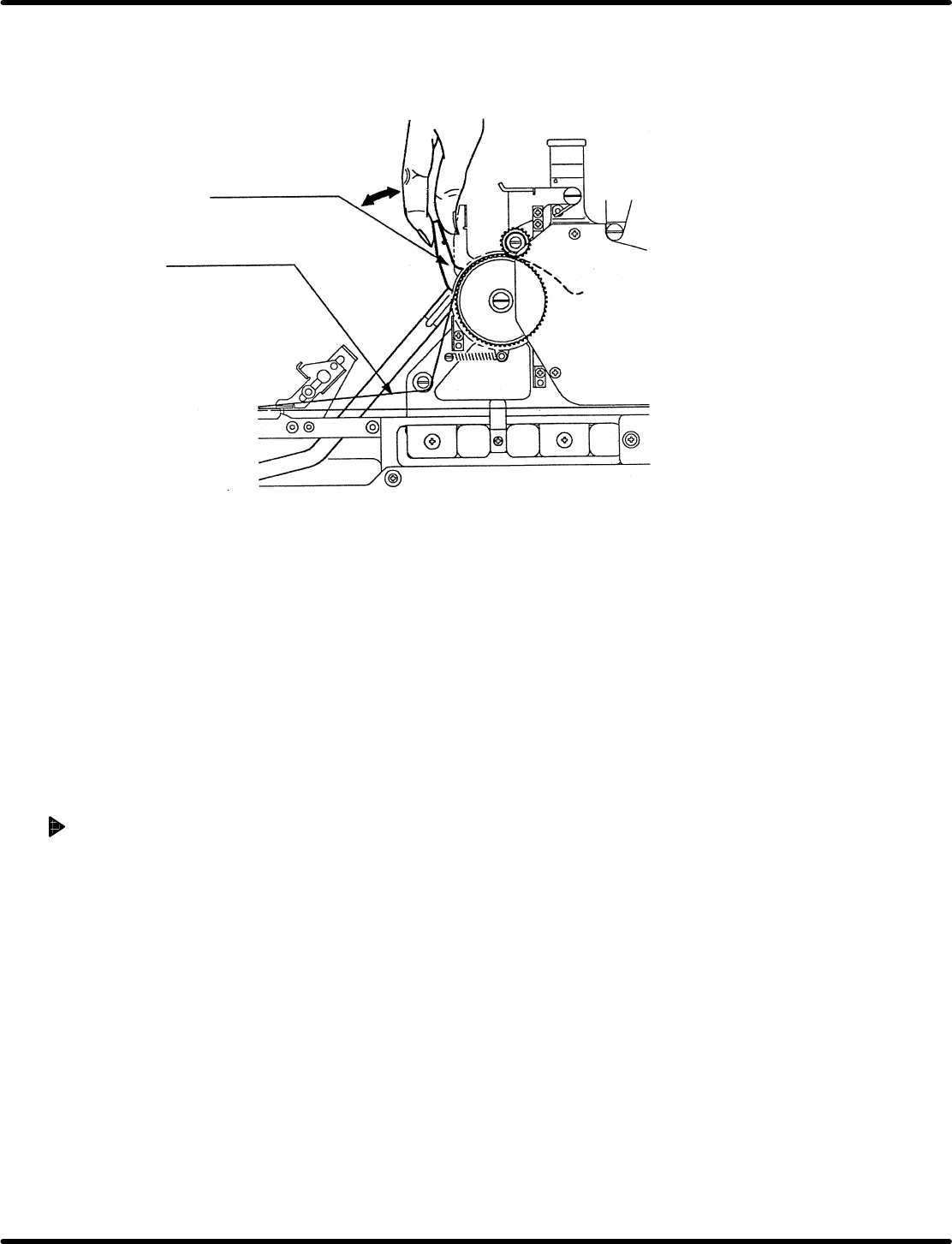
3. Rotate the positioning pin to adjust so that the feed wheel tooth may fall within the standard value range
of the stop position. (Secure the pin temporarily.)
4. Reciprocate the link lever about 10 times and make sure the position falls within the standard range
on the average.
Link lever
Carrier tape
5. Reciprocate the link lever slightly (not to let it be fed by one pitch) and rotate the back stop eccentric
pin so as not to move the tooth top of the feed wheel.
6. In this state, tighten the back stop eccentric pin temporarily and check that the tooth top of the feed
wheel does not move when reciprocating the link lever slightly.
If the tooth top of the wheel moves when the link lever is moved, make readjustment from the step 3.
7. After adjustment, re−tighten the back stop eccentric pin and positioning pin. The procedure is
completed after checking the followings.
=CHECK=
• Reciprocate the link lever and make sure the feed wheel tooth may fall within the standard value
of the stop position.
• When reciprocating the link lever slightly, check that the tooth of the feed wheel does not move.
(In other words, the wheel does not move by one pitch even if the link lever is moved.)
Adjustment Procedures [Motorized Feeder]
For motorized feeders, changing to the adjustment mode enables the position of the feed wheel to be
fine−adjusted with accuracy of 0.05 mm.
=REFERENCE=
Refer to the ‘Operation Manual of the Tape Feeder’ for details on the adjustment mode.
After adjustment, proceed the feed wheel and check the feed wheel tooth position every 12 teeth. Repeat
this check five times and make sure the position falls within the above−mentioned standard range.
=HINT=
For motorized feeders, setting the length of feed to 48 mm allows you to proceed to 12 teeth every
time feeding is carried out. Therefore, it is advisable to set the length of feed to 48 mm when
making checks.
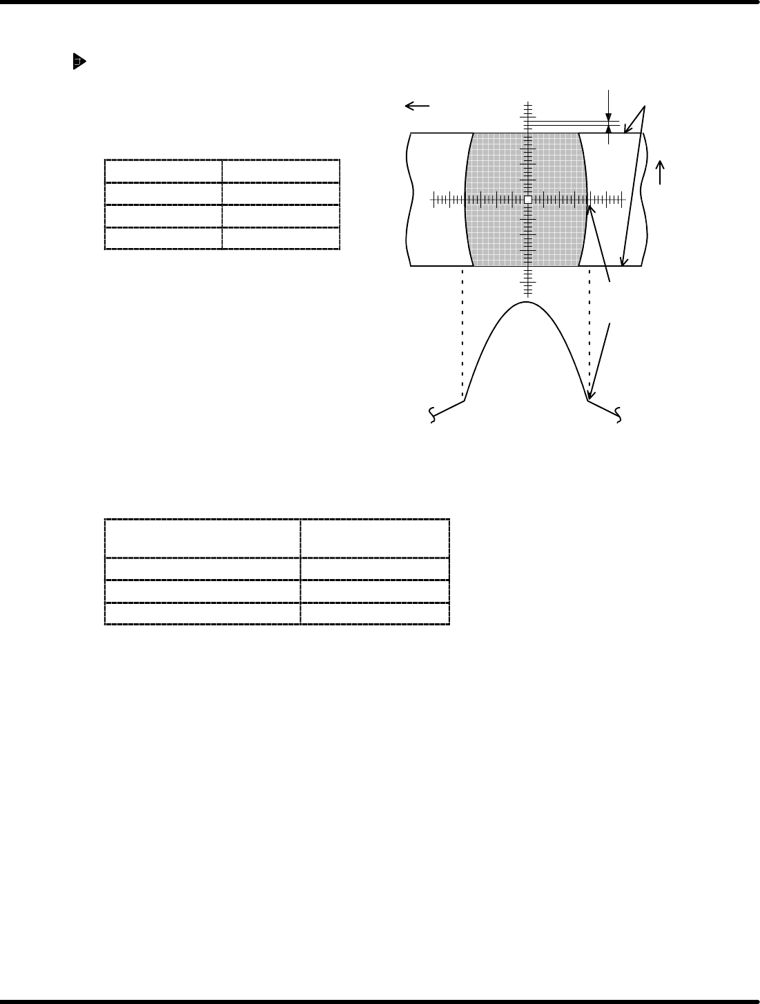
Y direction
(Feed direction)
0.025 mm
Graduation of scope: 0.025 mm/1 scale
Edge of wheel
X direction
(Tape width
direction)
Feeder Inspection Unit
4.1 Adjusting Wheel Position
4.1−14
DX1OEC−31−240−B0
4.1.6 Checking the Wheel Position in Tape Width Direction
Procedure
1. Wheel position check
Check if the edge of the wheel is within the
range of standard value.
=Specification=
Feeder type Standard
For 0603 ±0.1 mm
8to24mm ±0.15 mm
32 to 72 mm ±0.3 mm
2. If within the range
Hold down the lever to proceed the wheel by
six teeth and make checking similarly.
=REFERENCE=
• Check the wheel position for a complete
turn and if the wheel falls within the
standard range, the position is correct.
• Make checking every 12 crests regarding
the motorized feeders.
3. If out of the range
For the models in the table below, the wheel position in tape
feed direction can be adjusted.
Feeder type
Specifications
(Width)
Pneumatic feeder 8 mm * Note 1
Pneumatic double feeder 8mm
Motorized feeder 12 to 72 mm
* Note 1: Some feeders may not be adjusted depending on the time they were manufactured.
=REMARKS=
If the wheel position is deviated considerably due to fall or some impact, repair is needed.
=HINT=
Air may leak from the air conductor depending on the setting condition of the tape feeder on the
clamp stand.
In such a case, the position of the tape feeder is likely to be improper. Set it properly on the clamp
stand again.
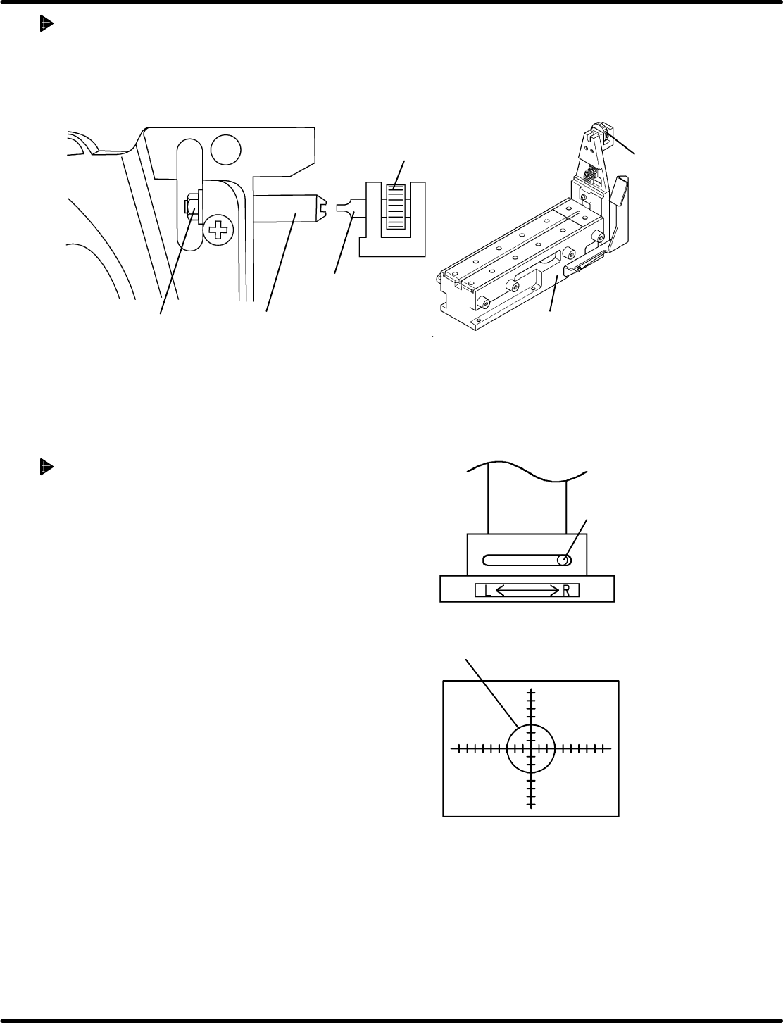
Pickup position V
R
Set the view select
lever to the R side.
4.1 Adjusting Wheel Position
Feeder Inspection Unit
4.1−15
DX1OEC−31−240−B0
Adjustment Procedures
1. Secure the positioning pin to the clamp stand with an attached screwdriver.
2. While securing the positioning pin with the screwdriver, loosen the nut using a wrench.
3. Since the positioning pin is decentered, rotate it with a screwdriver to adjust so that the feed wheel
tooth may fall within the standard value range of the stop position. Then secure the positioning pin.
Positioning pin
Nut
Screwdriver
Rotating knob
Clamp stand
Screwdriver
4.1.7 Checking Component Status at the Pickup Position
If the taping component is smaller than the camera
view (2 x 2.7 mm), the status of the fed component can
be checked at the pickup position.
Procedure
1. Attach the gauge jig to the clamp stand.
2. Set the camera view select lever to the R side.
3. Move the camera according to the V
R
of the gauge
jig and lock in place.
4. Attach a tape feeder containing the taping
components to the clamp stand.
This completes the preparation.
(For steps 1. through 4. , refer to ‘4.1.2’ and ‘4.1.3
Preparations for Inspection’.)
5. Set the panel switch according to the model of the
tape feeder to be checked.
Pressing “AUTO” allows you to check the status of
the fed taping components during feeding.
(For details on handling the panel switches, refer to
‘4.2 Tape Feeder Operation Check’.)