BM料架治具使用手册.pdf - 第82页
Connector Set bolt LED LED Bolt Nameplate Feeder side Camera view select lever 5.2 Routine Check Item Feeder Inspection Unit 5.2−3 DX1OEC−80−080−A0 Checking Accuracy Precision of the gauge jig should be checked once a ye…
Feeder Inspection Unit
5.2 Routine Check Item
5.2−2
DX1OEC−80−080−A0
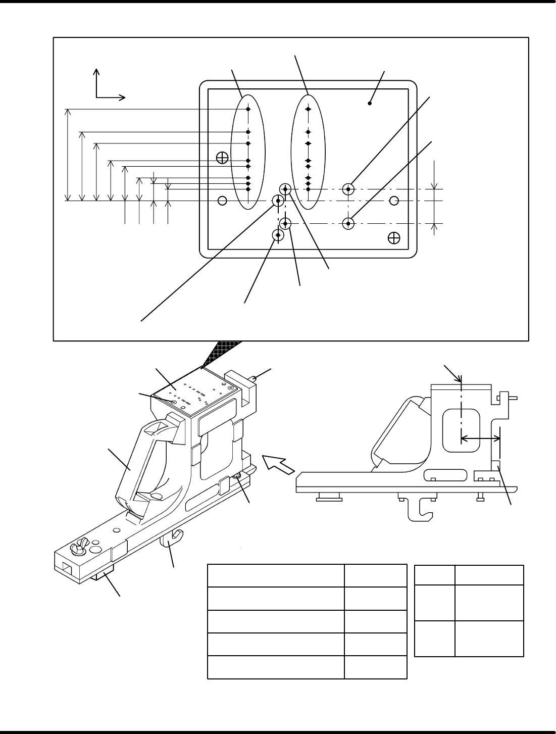
5.2.1 Gauge Jig Precision Check
A
72
56
44
32
16
8
72
56
44
32
24
16
12
V
MOTOR AIR
V
W
24
12
0603
8
W
34.2
26.2
20.2
14.2
11.5
7.5
5.5
3.5
10.75
X direction
(Width direction)
Y direction
(Feed direction)
Plate
V
L
: Pickup position (Double feeder, L side)
Pneumatic feeder
Motorized feeder
Pneumatic double feeder
(R side)
Pneumatic double feeder
(L side)
V
R
: Pickup position (Motorized feeder, pneumatic feeder, double feeders; R side)
Pneumatic double feeder
for 0603 (R side)
Pneumatic double feeder for 0603 (L side)
Block
Clamp claw
Guide pin
Gauge jig
Set screw of plate
Plate
Guide pin
The distance between the stopper and the center of the wheel
position and its accuracy vary with the feeder type as summarized in
the following tables.
Stopper
Center of wheel position
Motorized feeder
Feeder type
Pneumatic feeder
Distance A
38mm
78mm
54mm
62mm
Pneumatic double feeder
(8 mm)
Pneumatic double feeder
(For 0603)
Width
8mm
Accuracy (Both X
and Y directions)
±0.05mm
±0.025mm
12 to
72mm
Connector
Set bolt
LED
LED
Bolt
Nameplate
Feeder side
Camera view
select lever
5.2 Routine Check Item
Feeder Inspection Unit
5.2−3
DX1OEC−80−080−A0
Checking Accuracy
Precision of the gauge jig should be checked once a year. Contact Panasonic service office.
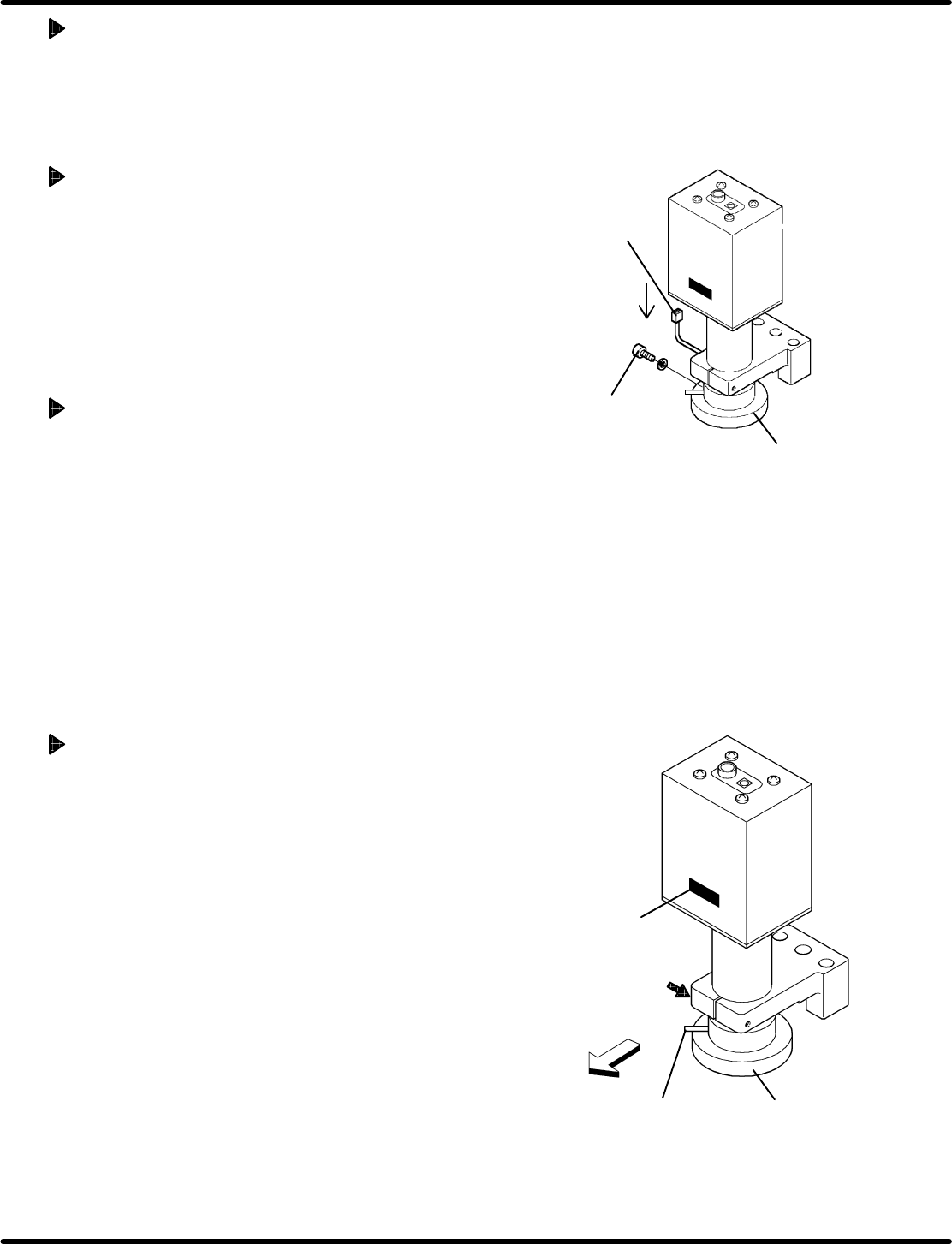
5.2.2 Replacing LED in the Camera
Replace the LED after about 10,000 hours of use and if clear view cannot be obtained.
Removing Procedure
1. Disconnect the connector.
2. Remove the set bolt at the LED.
3. Pull out the LED downward.
Attaching Procedure
Mount a new LED in reverse order to the removing.
(Be sure to install the LED in proper orientation.)
=REFERENCE=
LED is a consumable part.
Name: LED
Part No.: N940Q3A03706
Replacing the Camera (Reference)
1. Detach the LED. (Refer to ‘" Removing Procedure’
above.)
2. Loosen the bolt securing the camera.
3. Withdraw the camera upward.
4. Remove the LED on a new camera and attach it with the
nameplate faced on the feeder side.
5. Reattach the LED in the reverse order of removal.
6. Make adjustment by referring to ‘5.1.1 " Adjusting the
Camera Position’.

Feeder Inspection Unit
5.2 Routine Check Item
5.2−4
DX1OEC−80−080−A0
= MEMO =