BM料架治具使用手册.pdf - 第77页
Set the view select lever in the middle between L and R. NG (Adjustment is required.) T wo marks appear dimly . Feeder Inspection Unit 5.1 Daily Check Items 5.1−2 DX1OEC−80−070−A0 5.1.1 Adjusting the Camera Position Chec…
5.1 Daily Check Items
Feeder Inspection Unit
5.1−1
DX1OEC−80−070−A0
5.1 Daily Check Items
DX1OEC−80−070−A0
Sentence No.
No. Check item Check method and criteria Frequency
1 Gauge jig
• Ensure that there are no nicks or chip components
adhering to the surface (bottom side) of the gauge jig
or stopper.
At the start of
operation and when
detaching/attaching
gauge jig
2 Clamp stand
• Ensure that chip components are not adhering to the
surface to which feeder of the clamp stand is to be
loaded or air conductor.
Must be free of flaw or deformation due to nick.
• Ensure that there are no foreign matters or chip
components adhering to the clamp roller of the clamp
stand.
At the start of
operation and when
detaching/attaching
tape feeder
3 Camera adjustment
• Checking holding
position
• Set the gauge jig onto the clamp stand and adjust
the camera to the pickup position. Then, while
switching the view select lever between L and R,
check if the camera position is correct.
(Refer to ‘4.1.3’.)
• Adjust the camera position if necessary.
(Refer to ‘5.1.1 Adjusting Camera Position’.)
At the start of
operation
• Check camera
lighting
• Check if the LED is lit and adjust the intensity.
Adjust the intensity of the camera on the monitor as
necessary.
At the start of
operation
Set the view
select lever in
the middle
between L and
R.
NG (Adjustment is required.)
Two marks
appear dimly.
Feeder Inspection Unit
5.1 Daily Check Items
5.1−2
DX1OEC−80−070−A0
5.1.1 Adjusting the Camera Position
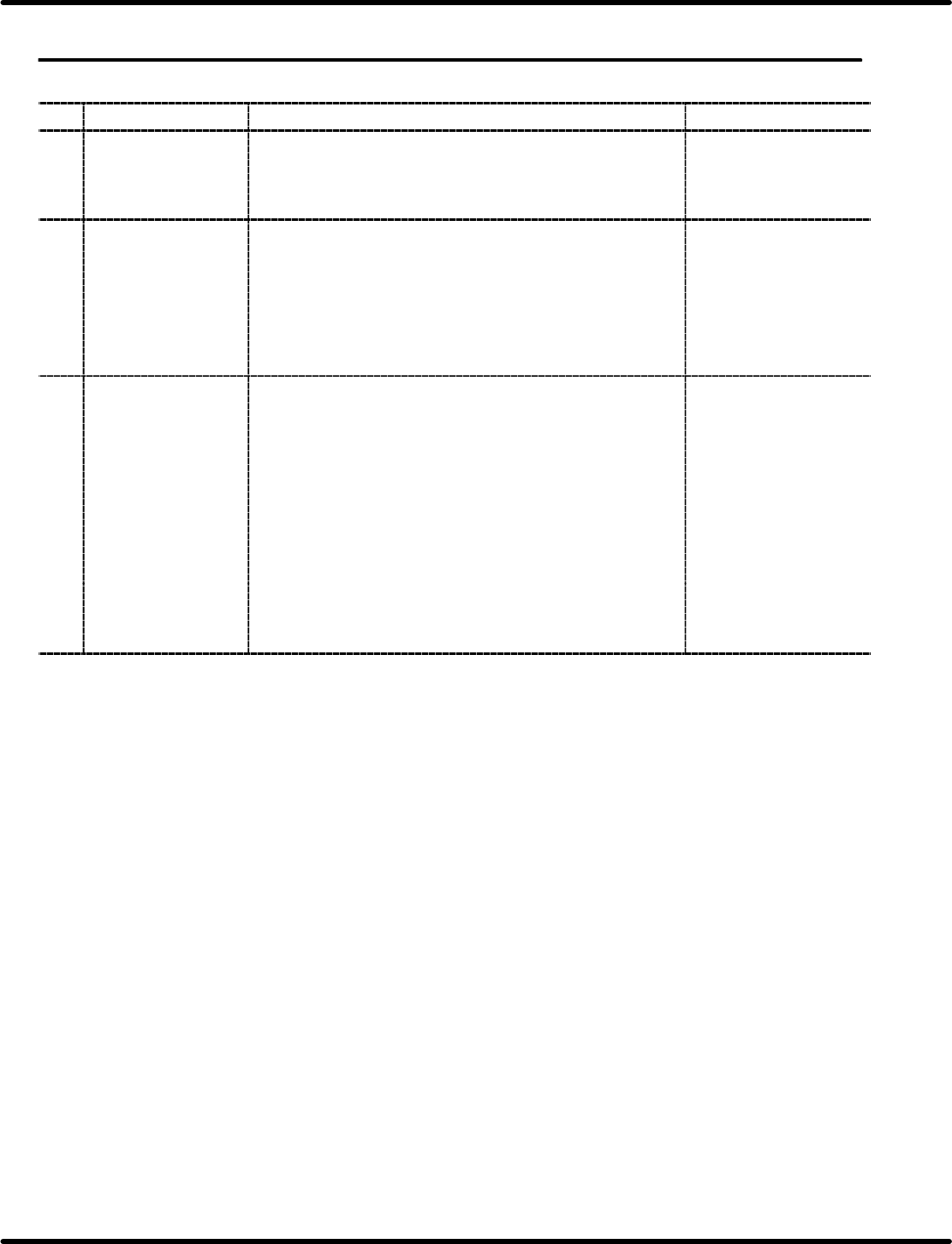
Checking the Camera Position
=REFERENCE=
Refer to ‘4.1.3 Adjusting the Camera Position’ for details.
1. Attach the gauge jig to the clamp stand.
2. Set the camera view select lever to the R side.
3. Align the gauge hole (V
R
) with the center of the monitor by adjusting the knobs (X, Y and Z).
4. Positioning is correct when the gauge hole (V
L
) appears at the center of the monitor when the camera
view select lever is set to the L side.
OK
OK: Two marks appear to be overlapped
and matched.
NG: Two marks appear to be misaligned.
After switching camera
view select lever (L)
Before switching camera
view select lever (R)
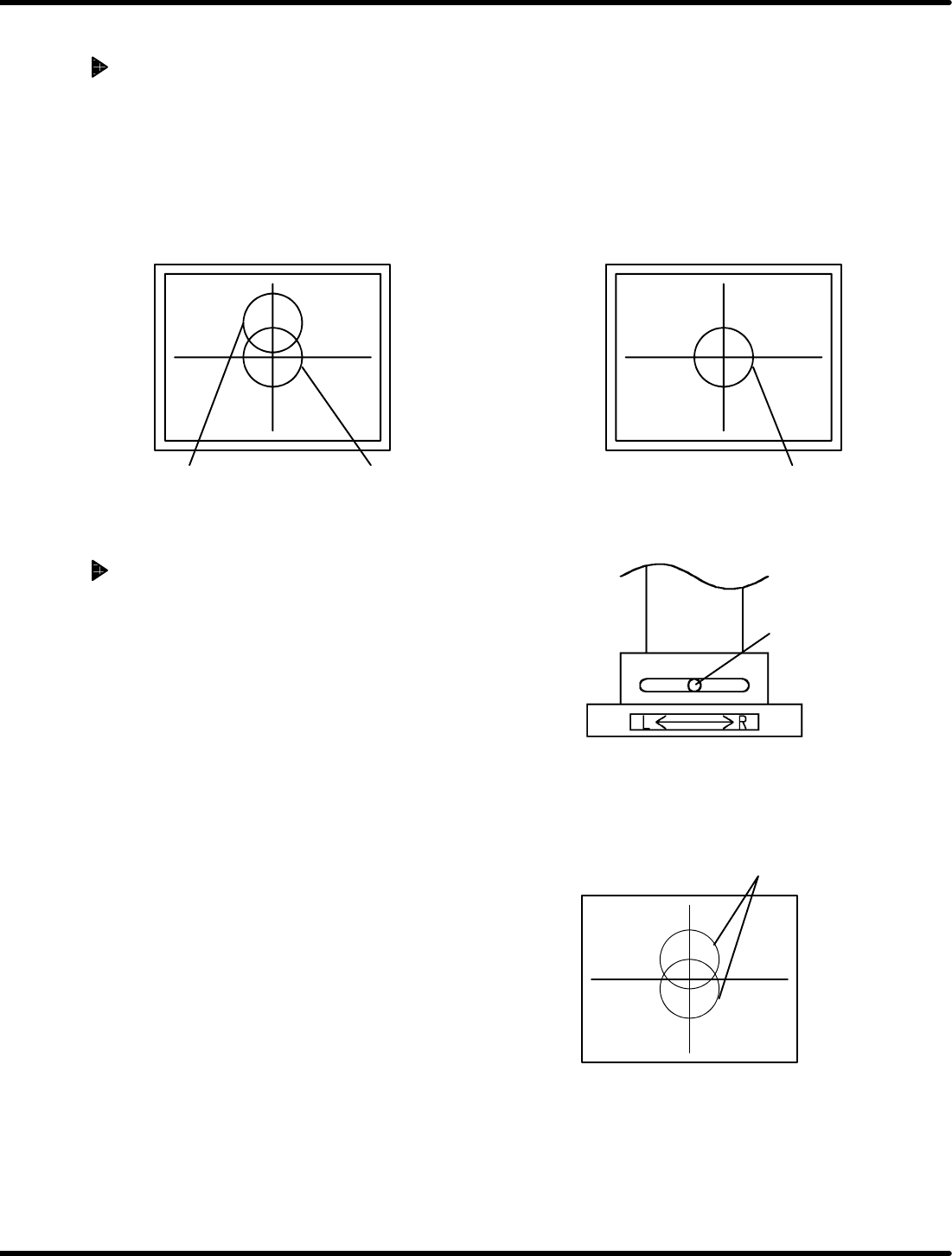
Adjusting the Camera Position
1. With the camera secured at the pickup position (see step
3in‘" Checking the Camera Position’), set the view
select lever almost in the middle position between L and
R.
2. At this time, both the gauge holes V
L
and V
R
appear
dimly on the monitor.
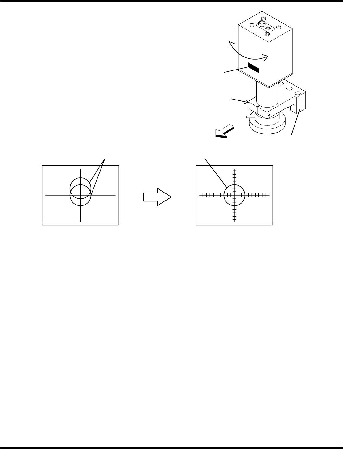
Z slider
Feeder side
Bolt
(Loosen the bolt
during adjustment and
tighten when fixing the
camera.)
Nameplate
Rotate the
camera.
5.1 Daily Check Items
Feeder Inspection Unit
5.1−3
DX1OEC−80−070−A0
3. Loosen the bolt for locking the camera of the Z
slider to enables the camera to be rotated.
While observing the display on the monitor, turn
the camera until the gauge holes V
L
and V
R
match. Then, tighten the bolt to secure the
camera.
=REMARKS=
Install the camera so that the nameplate
can be placed on the feeder side as shown
in the drawing right.
Two marks appear to be misaligned.
Adjust so that two
marks overlap.
OK (After adjustment)
Positioning is OK if two holes overlap.
NG (Adjustment is required.)
=CHECK=
Perform the procedure in ‘" Checking the Camera Position’ again to make sure the camera for
proper position. If there is nothing wrong with the adjustment, complete the setting.