BM料架治具使用手册.pdf - 第69页
Feeder Inspection Unit 4.2 T ape Feeder Operation Check 4.2−10 DX1OEC−31−250−A0 Operation Check for the T ape Exhaust Detection Sensor If the tape in the feeder is exhausted, the ‘T APE’ lamp will come on. As shown in th…
4.2 Tape Feeder Operation Check
Feeder Inspection Unit
4.2−9
DX1OEC−31−250−A0
4.2.5 Motorized Feeder
Feed Operation Check
1. Control panel switch settings
Switch
Setting
CASSETTE TYPE Set to “1”.
FEED TIMES Set to “1”.
PEEL SELECT Set to “0”.
LED ON OFF (Do not push.)
FEED OFF (Do not push.)
PEEL OFF (Do not push.)
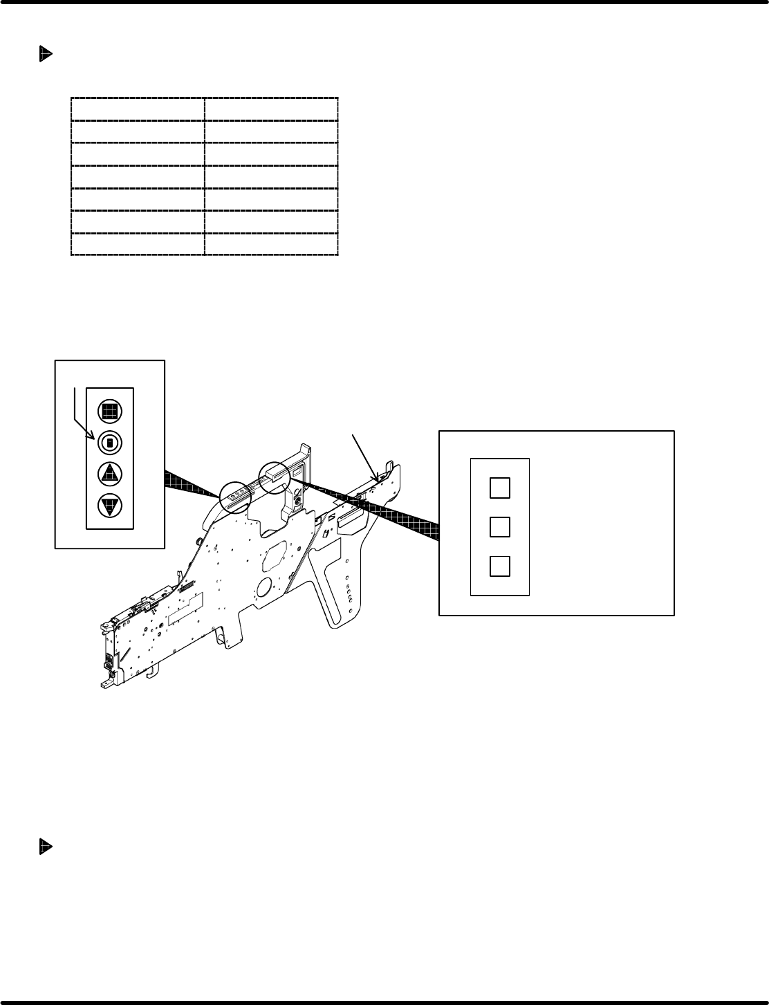
2. Operation check
Pressing “AUTO” will make feeding for the length specified on the feeder side and then will stop.
When operation finishes normally, the ‘FEED OK’ lamp will come on.
4
−
+
Status indicator
lamp
=HINT=
Set the amount of
feed on the f eeder
side within the
allowable range.
Dial switch
Motorized feeder
Tape end detection lever
=HINT=
• If wanting to reattempt the feed operation with “AUTO”, set so that the tape end detection lever
will detect a tape exhaustion beforehand. (Doing so prevents an operation error of the motorized
feeder.)
• If the ‘TIME UP’ or ‘ERROR’ lamp lights up after pressing the “AUTO” switch, either the “FEED”
or “PEEL” switch is ON. In such a case, turn it OFF.
Operation Check for the Feeder Select Lamp
Turning ON the “LED ON” switch will light up the lamp while the switch is held down. When the “LED
ON” switch is OFF (Turns to OFF if released.), the feeder select lamp will go out.
Feeder Inspection Unit
4.2 Tape Feeder Operation Check
4.2−10
DX1OEC−31−250−A0
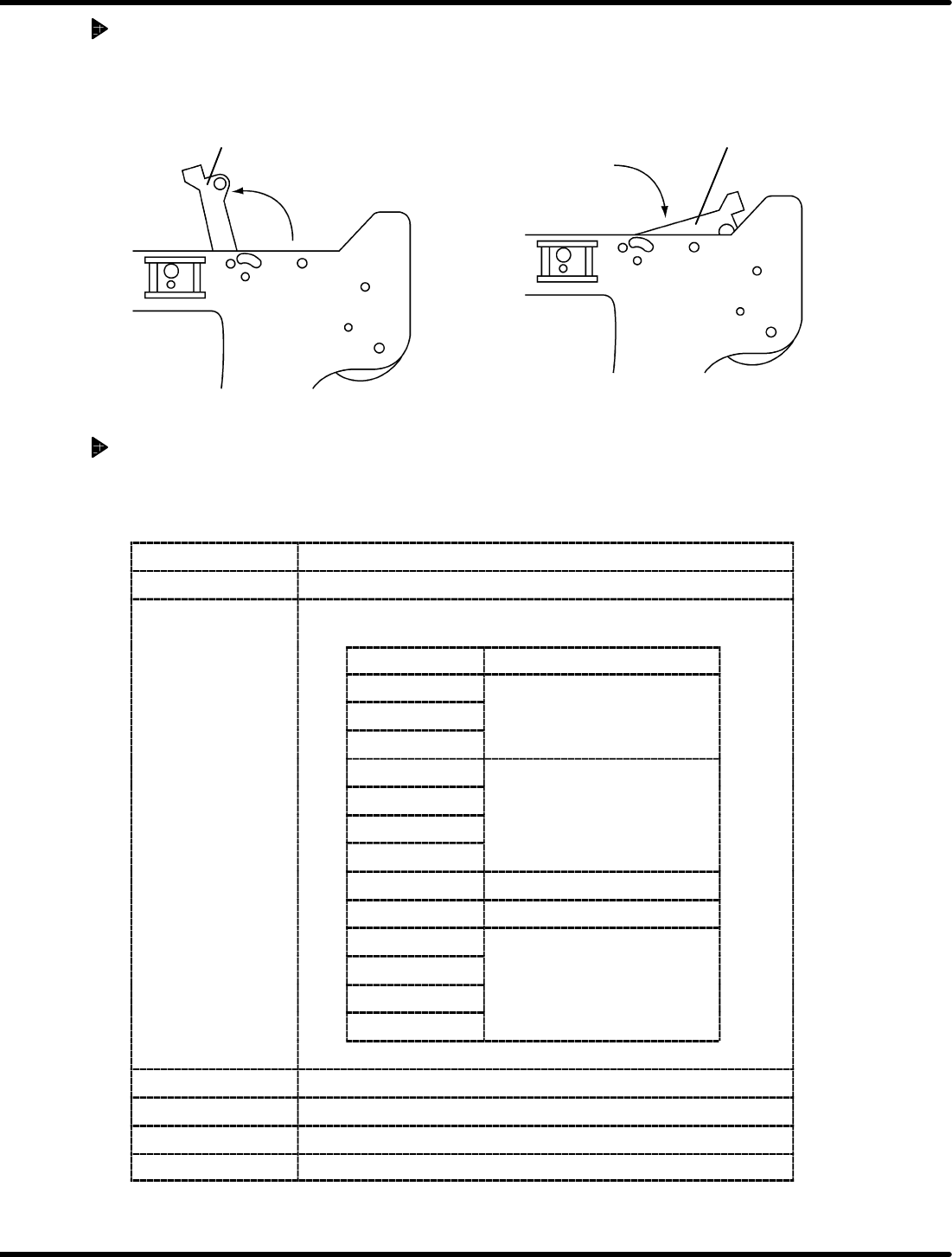
Operation Check for the Tape Exhaust Detection Sensor
If the tape in the feeder is exhausted, the ‘TAPE’ lamp will come on.
As shown in the drawing below, check the sensor for proper operation by using the tape end detection
lever.
‘TAPE’ lamp goes out.
‘TAPE’ lamp comes on (When tape exhaustion
occurs.)
Tape end detection lever
Tape end detection lever
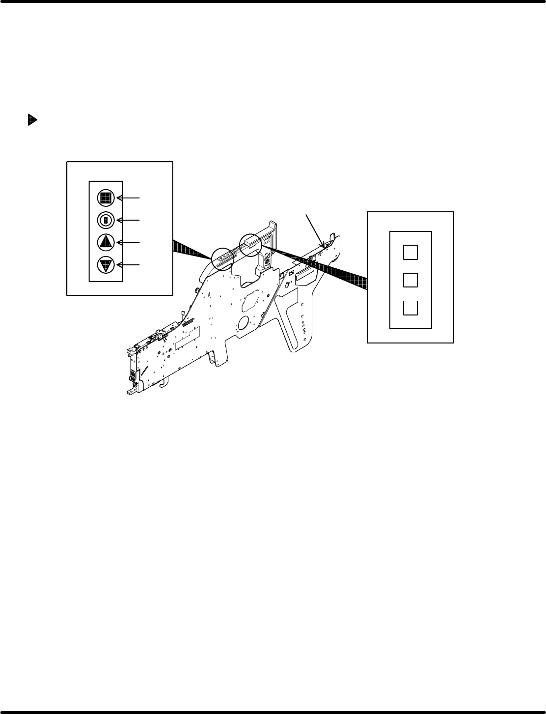
Motorized Feeder (Pneumatic Feeder Mode)
The motorized feeder includes the cylinder mode which enables the same operation signal as the
pneumatic feeder to be received.
When using the motorized feeder in the cylinder mode, set the switches on the control panel as follows:
Switch
Setting
CASSETTE TYPE Set to “1”.
FEED TIMES Can be set between 1 and 4 according to the feed pitch
specified on the feeder side.
Feed pitch (mm) ‘FEED TIMES’ value
4
8
1
12
16
20
2
24
2
28
32 4
36 3
44
48
4
52
4
56
PEEL SELECT Set to “0”.
LED ON OFF (Do not push.)
FEED OFF (Do not push.)
PEEL OFF (Do not push.)
4.2 Tape Feeder Operation Check
Feeder Inspection Unit
4.2−11
DX1OEC−31−250−A0
=REMARKS=
• Refer to the ‘Operation Manual of the Tape Feeder’ for details on the cylinder mode.
• When the motorized feeder in the cylinder mode has been set to the clamp stand, pressing “AUTO”
will result in an operation error if the ‘FEED TIMES’ values have not been set properly. (The
‘ERROR’ lamp will come on.)
When this happens, detach the motorized feeder once from the clamp stand and set the ‘FEED
TIMES’ values correctly.
Changing the Feed Pitch of the Motorized Feeder (Reference)
Here following describes how to change the feed pitch with the motorized feeder loaded to the feeder
adjust unit.
4
Dial switches
Control switches
Motorized feeder
Tape end detection lever
−
+
(1)
(2)
(3)
(4)
1. Using the dial switches on the motorized feeder, change the feed pitch to the desired value.
(At this time, the button (2) LED flashes in red four times.)
2. Press the button (1) on the motorized feeder (for more than two seconds) to determine the pitch.
The button (2) LED stops flashing.
3. This completes the setting.
=HINT=
The feed pitch can be changed with the dial switches with the motorized feeder detached from the
clamp stand.