BM料架治具使用手册.pdf - 第64页
4.2 T ape Feeder Operation Check Feeder Inspection Unit 4.2−5 DX1OEC−31−250−A0 Feeder select lamp LED Cylinders and Sensors (Pneumatic Feeder) Forward limit sensor Reverse limit sensor Reverse Forward Adjust screw Revers…
Feeder Inspection Unit
4.2 Tape Feeder Operation Check
4.2−4
DX1OEC−31−250−A0
4.2.3 Pneumatic Feeder
Checking Feed Operation
1. Control panel switch settings
Set the switches on the control panel according to the specifications of the feeder as shown in the
table below.
Switch
Normal
(other than 32 mm paper)
32 mm paper
CASSETTE TYPE Set to “1”. 1
FEED TIMES Can be set between 1 and 4. Can be set between 1 and 4.
PEEL SELECT Set to “0”. Set to “1”.
LED ON OFF (Do not push.) OFF (Do not push.)
FEED OFF (Do not push.) OFF (Do not push.)
PEEL OFF (Do not push.) OFF (Do not push.)
2. Operation check
• Operation check (Feeders under normal setting)
Pressing the “AUTO” switch will turn ON the feed cylinder to move it from the reverse limit to the
forward limit. In 20 ms after the feed cylinder reaches the forward limit, it will turn OFF to move
back to the reverse limit. The tape feeder will repeat feeding at the time set by the “FEED
TIMES” switch and will terminate action.
When operation finishes normally, the ‘FEED OK’ lamp will come on.
• Operation check (32 mm paper feeders)
After feeding the tape for the preset count, the feed cylinder will move to the reverse limit and at
the same time, the peeling cylinder will turn ON to move from the forward limit to the reverse
limit. In 20 milliseconds after the cylinder reaches the forward limit, the cylinder will turn OFF to
move back from the forward limit to the reverse limit and will terminate action.
When operation finishes normally, the ‘FEED OK’ lamp will come on.
4.2 Tape Feeder Operation Check
Feeder Inspection Unit
4.2−5
DX1OEC−31−250−A0
Feeder select
lamp
LED
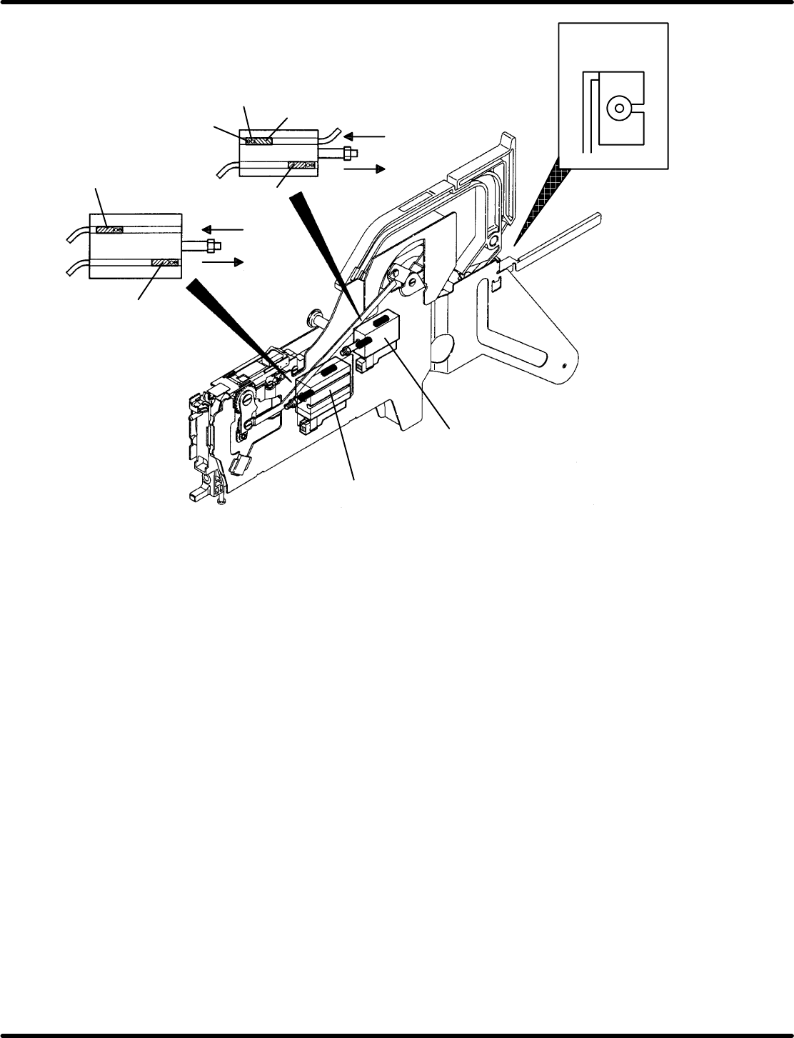
Cylinders and Sensors (Pneumatic Feeder)
Forward
limit sensor
Reverse limit
sensor
Reverse
Forward
Adjust screw
Reverse limit
sensor
Forward limit
sensor
Feed cylinder
Peeling cylinder
(Only for feed/peeling feeder)
Reverse
Forward
=HINT=
• If the ‘ERROR’ lamp lights up during operation, the probable cause is the space between the forward
limit and reverse limit sensors is too narrow.
If the ‘TIME UP’ lamp lights up during operation, either of these sensors has become slow to react
or irresponsive.
• If the ‘TIME UP’ or ‘ERROR’ lamp lights up after pressing the “AUTO” switch, either the “FEED”
or “PEEL” switch is ON. In such a case, turn it OFF.
Feeder Inspection Unit
4.2 Tape Feeder Operation Check
4.2−6
DX1OEC−31−250−A0
Operation Check for the Cylinder Forward/Reverse Limit Sensors
1. Control panel switch settings
Set the switches on the control panel according to the specifications of the feeder as shown in the
table below.
Switch
Feed cylinder Peeling cylinder
(32 mm paper)
CASSETTE TYPE Set to “1”. Set to “1”.
FEED TIMES Set to “1”. Set to “1”.
PEEL SELECT Set to “0”. Set to “1”.
LED ON OFF (Do not push.) OFF (Do not push.)
2. Operation check
Operation check for the feed cylinder forward/reverse limit sensors
• Turning ON the “FEED” switch will move the feed cylinder to the forward limit and then will stop.
If the ‘STATUS’ lamp comes on, the operation and the position of the forward limit sensor are correct.
• Turning OFF the “FEED” switch will move the feed cylinder to the reverse limit and then will stop.
If the ‘STATUS’ lamp comes on, the operation and the position of the reverse limit sensor are correct.
• The “FEED” switch can be held in the ON state. Usually, set it in the OFF state (do not push).
Operation check for the peeling cylinder (32 mm paper)
• Turning ON the “PEEL” switch will move the peeling cylinder to the forward limit and then will stop.
If the ‘STATUS’ lamp comes on, the operation and the position of the forward limit sensor are correct.
• Turning OFF the “PEEL” switch will move the peeling cylinder to the reverse limit and then will stop.
If the ‘STATUS’ lamp comes on, the operation and the position of the reverse limit sensor are correct.
• The “PEEL” switch can be held in the ON state. Usually, set it in the OFF state (do not push).
If any problem is observed in the forward/reverse limit sensors of t he feed cylinder and peeling
cylinder, they need be checked by us. Contact Panasonic service office.
Operation Check for the Feeder Select Lamp
Turning ON the “LED ON” switch will light up the lamp while the switch is held down. When the “LED
ON” switch is OFF (Turns to OFF if released.), the feeder select lamp will go out.