BM料架治具使用手册.pdf - 第51页
Graduation of scope: 0.025 mm/1scale 0.025 mm Y direction (Feed direction) Edge of wheel Feeder Inspection Unit 4.1 Adjusting Wheel Position 4.1−8 DX1OEC−31−240−B0 4.1.5 Checking the Wheel Position in T ape Feed Directio…
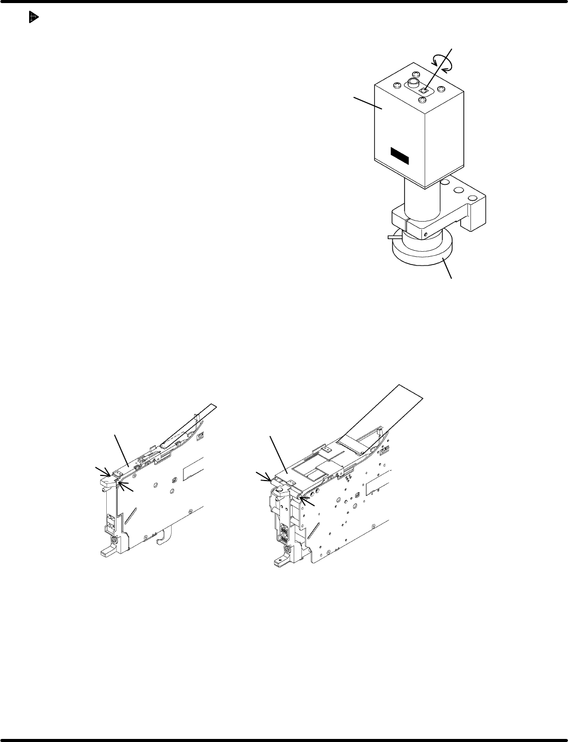
Camera
LED
Varistor for adjusting light
intensity
4.1 Adjusting Wheel Position
Feeder Inspection Unit
4.1−7
DX1OEC−31−240−B0
Adjusting LED
• If the holes in the gauge or object to be checked cannot
be seen clearly on the monitor, adjust the brightness of
the LED of the camera.
• Adjust the brightnes s by turning the varis tor for
adjusting light intensity.
• Use a Phillips screwdriver when turning the varistor for
adjusting light intensity.
4.1.4 Removing Tape Retainer
Because of the structure of the feeder, it may be necessary to remove the tape retainer or tape guide
when checking the wheel position. Observe the below procedure, if applicable, to remove them before
checking.
Regarding the following feeders, the tape guide need be removed.
• Motorized feeders (12 to 72 mm tape)
Set screw
Set screw
Set screw
Set screw
12 − 24 mm 32 − 72 mm
Tape guide
Tape guide
Removing the set screws permits you to detach the tape guide from the feeder.
=REFERENCE=
After inspecting or checking, reattach the tape guide reversing the removal procedure.
Concerning the following feeders, the feed wheel can be seen with the tape guide loaded normally.
• Pneumatic feeder
• Pneumatic double feeder
Remove the taping component and hook the tape guide.
Graduation of scope: 0.025 mm/1scale
0.025 mm
Y direction
(Feed direction)
Edge of
wheel
Feeder Inspection Unit
4.1 Adjusting Wheel Position
4.1−8
DX1OEC−31−240−B0
4.1.5 Checking the Wheel Position in Tape Feed Direction (Y
Direction)
Wheel Position Check
Check if the edge of the wheel is within the range of
standard value when it is positioned symmetrically with
respect to the cross hairs.
=HINT=
Make use of dimension gauges.
(Refer to ‘2.4 DIMENSION GAUGES FOR
OHP’.)
1. If within the range
Hold down the lever to proceed the wheel by five
crests and make checking similarly. (‘4.2 Tape
Feeder Operation Check’.)
=CHECK=
Repeat the step six times and if the edge of the
wheel falls within the standard range every time,
the position is correct.
2. If out of the range
Adjust the wheel position according to the below figure.
The standard range is described on pages 4.1−9 to
4.1−11.
=HINT=
Before measuring, ensure that the air conductor
of the feeder and that of the clamp stand have
been fitted properly without any gap.
=HINT=
Air may leak from the air conductor depending on the setting condition of the tape feeder on the
clamp stand.
In such a case, the position of the tape feeder is likely to be improper. Set it properly on the clamp
stand again.
4.1 Adjusting Wheel Position
Feeder Inspection Unit
4.1−9
DX1OEC−31−240−B0
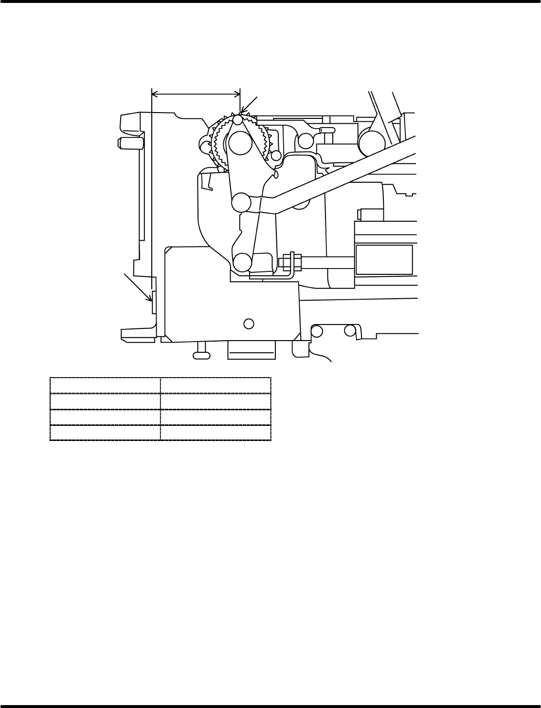
=Specification=
Pneumatic feeder
Measure the dimension ‘A’ in the illustration below.
A
Air conductor
Feed wheel tooth
(center line of feed wheel)
Feeder type (width)
Standard value (A)
8mm 54±0.1 mm
12 to 24 mm 54±0.15 mm
32 to 72 mm 54±0.3 mm