AL1_SiplaceX-en.pdf - 第143页
1 - 53 S tudent Guide SIPLACE X Edition 02/2005 4 Coll ect &Place-Head 6/12 53 4.4 Adjustment s 4.4.1 Description of the PCB bo ards on the 6/12 C&P head All described adjustment s in this chapter are head spezif…
1 - 52
Student Guide SIPLACE X
4 Collect &Place-Head 6/12 Edition 02/2005
52
4.3.37 Description air kiss control
Air kiss control at placement: 4
Value “0” mean the blast air valve don‘t switch on.
(1) Value “1-50” mean blast air valve is switched OFF when stepper motor valve drive start to
move.
(2) Value “51-150” mean blast air valve is switched OFF when stepper motor valve drive moved
for 90 degree.
(3) Value. “151-255 mean blast air valve is switched OFF when stepper motor valve drive moved
for 180 degree.
Or at light barrier top.
No value “----” (from converting 501/502 to 503 format) mean same mode than
(3) (existing
standard).
Air kiss control at return component! (not reject) 4
(4) Value and description like (1)
(5) Value and description like (2)
(6) Value. “151-255” mean blast air valve is switched OFF when stepper motor valve drive moved
for 180 degree.
Please Note
More Information about the air kiss control see chapter C&P head with (Flow chart).
Notes:
1 - 53
Student Guide SIPLACE X
Edition 02/2005 4 Collect &Place-Head 6/12
53
4.4 Adjustments
4.4.1 Description of the PCB boards on the 6/12 C&P head
All described adjustments in this chapter are head spezific and are necessary here for the
6/12 C&P head.
4.4.1.1 Headadapter for 6/12 C&P head
At the head modularity we can use the same head adapter for the 6 and 12 segment C&P heads.
The head adapter must be exchanged if you mounting the Twin head or the C&P 20 head.
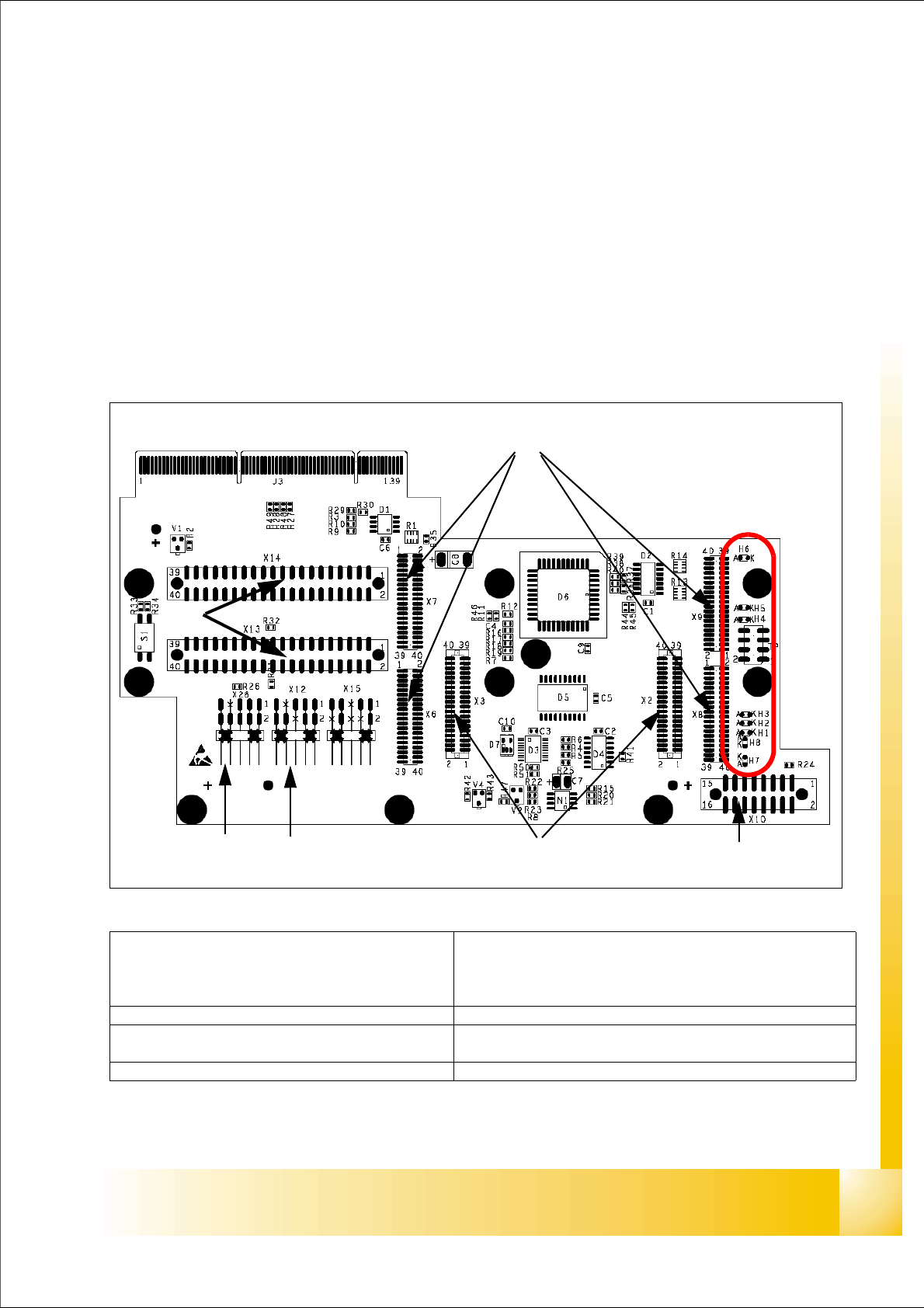
Fig. 4.4 - 1 Headadapter for 6/12 C&P head(03019066-0x)
1
2
45
3
6
7
LED‘S
(1)X6 -X9 Connector for CAN Prozessor-board’
80C515C 8Bit not mounted, because these
function make the 16 Bit processor on the head
interface C500.
(2)X2/X3 Connector for the stepping motor board
(3)X10 Connector vacuum board (4) X12 Dp station (motor, track signale)
(5)X26 Option component sensor (6)X13/14 connector for the flat cable to the intermedi-
ate distribution boardr
(7)Connector to the headinterface C500 (8)
1 - 54
Student Guide SIPLACE X
4 Collect &Place-Head 6/12 Edition 02/2005
54
Description LED‘s on the head adapter: 4
– H6 -LZOS Light barrier Z-axis upper stop
– H5 -LZUS Light barrier Z-axis down position
– H4 -LSM Stepper motor board not connected
– H3 -LSZD Light barrier Swivel in for turning at DP-station
– H2 -LSVZ Light barrier Vacuum / air kiss Z-axis
– H1 -LSVA Light barrier Vacuum / air kiss reject position
– H8 -P15_F 15V Power supply
– H7 -C167
4.4.1.2 Stepping motor board
The stepping motor board for the valve drivers and the swivel function on the DP station is moun-
ted onto the head adapter. Now, the functions are controlled via the 16 Bit processor board on the
head interface.
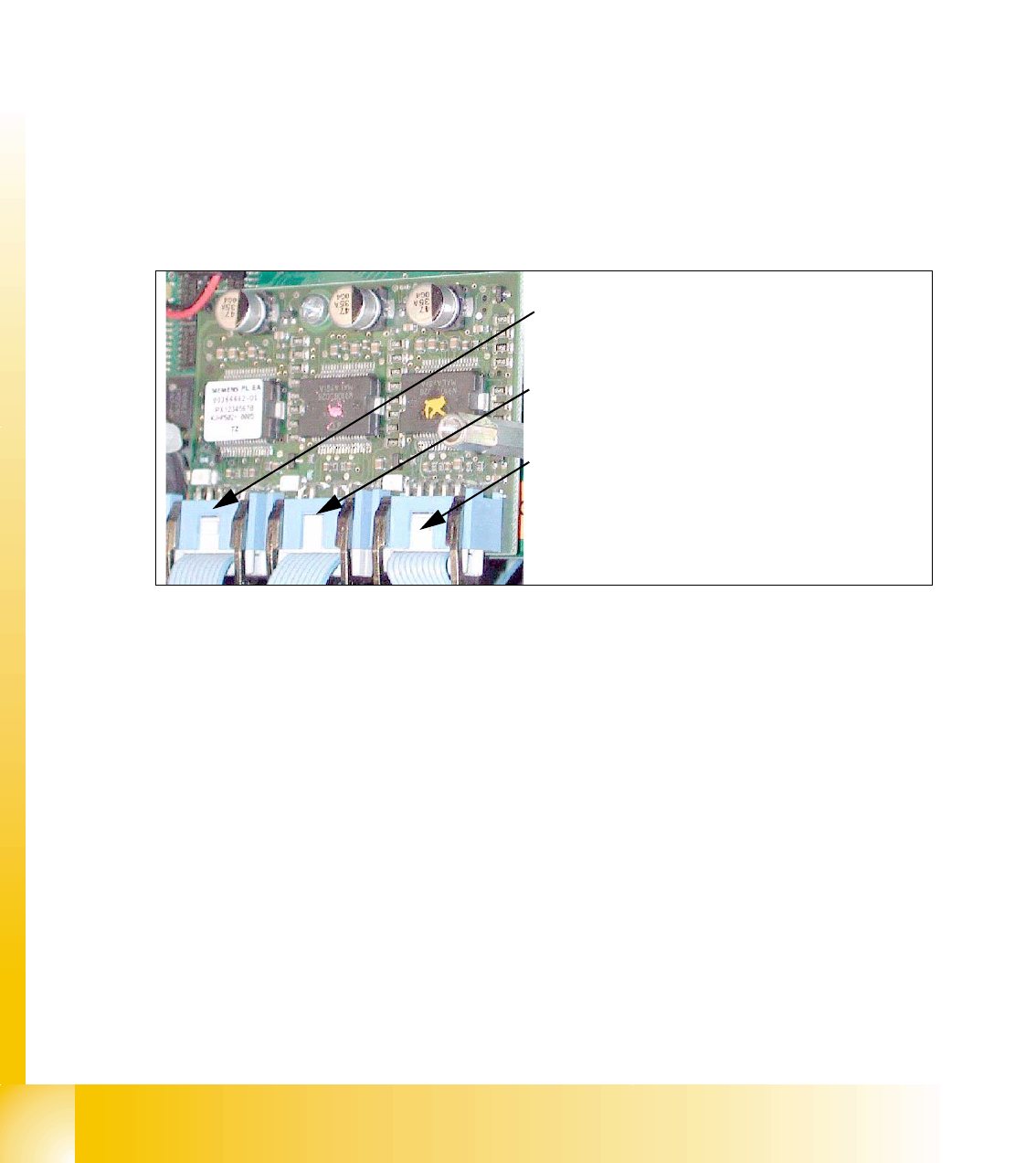
Fig. 4.4 - 2 Stepping motor board
2
3
1
Stepping motor rejectposition
(for X3/X2. X4 and HF-machine)
Stepping motor pick up-, placement-
(and reject position HF/HF3)
Stepping motor DP-axis