AL1_SiplaceX-en.pdf - 第264页
1 - 10 S tudent Guide SIPLACE X 7 Sitest Ausgabe 02/2005 10 7.2.1 Calibration in general Fig. 7.2 - 1 General sequence to calibrate the machine Note: Since the head modularity concept mea ns that eith er a T win Head or …

1 - 9
Student Guide SIPLACE X
Ausgabe 02/2005 7 Sitest
9
7.2 Calibration
WARNING
During some of the procedures the gantries will move.
Therefore, before you begin with any of these procedures make sure that you and everyone else
stay physically clear of the travel range of the gantries.
RISK OF INJURY!
Also, sure, that no objects are in the way. 7
7
Note:
Before you begin with the calibration, you must reference the heads and the gantries.
During calibration, unused gantries will automatically be moved to their parking position.
For a complete calibration of the placement system, the SITEST test program provides the func-
tion
"Calibrate machine..." which allows you to start all calibration functions from the menu "Calibrate
entire machine". 7
Equipment and Testing Tools
– Test program SITEST, version 601.xx
– Calibration tools
Version II transparent S/F/HS --> 00316308-03
Version III nontransparent HF/X with C&P6/12 and Twin head --> 03010565-01
Version SST 23 C&P 20 head --> 03034148-01
– Nozzles, type 1235, 956, 517,518, Nozzle for Zero point correction Twin Head D-Axis
03008862-03)
– Gauge (
– PCB with a width 100 mm
1 - 10
Student Guide SIPLACE X
7 Sitest Ausgabe 02/2005
10
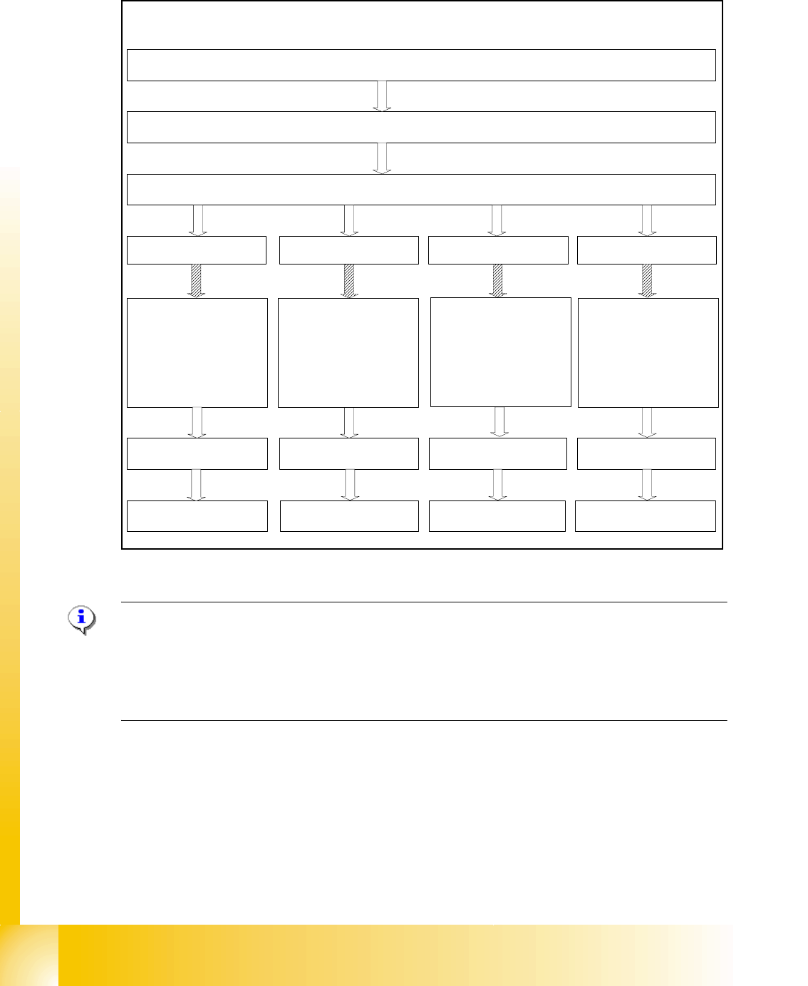
7.2.1 Calibration in general
Fig. 7.2 - 1 General sequence to calibrate the machine
Note:
Since the head modularity concept means that either a Twin Head or a C&P head can be fitted to
each gantry, the functions displayed for processing area 1(PA1) and processing area 2 (PA2) re-
spectively may vary. The functions described for PA1 and PA2 below apply for a Twin Head con-
figured on gantry 3 and a C&P head configured on gantry 1 on a X2 machine.
Sequence of calibrate the Siplace X machine with SW 601
Preperation the machine
All heads and cameras..
Sitest: Button "Calibrate machine...."
Calibrate and
teach of positions
(conveyor edges,
conveyor width,
PCB reference
corner, pick-up
positions)
PCB Mapping
Head Mapping
Gantry 1
(X2/X3/X4)
Gantry 2
(X4)
Gantry 4
(X3/X4)
Gantry 3
(X2/X3/X4)
PCB Mapping PCB Mapping PCB Mapping
Head Mapping Head Mapping Head Mapping
Calibrate and
teach of positions
(conveyor edges,
conveyor width,
PCB reference
corner, pick-up
positions)
Calibrate and
teach of positions
(conveyor edges,
conveyor width,
PCB reference
corner, pick-up
positions)
Calibrate and
teach of positions
(conveyor edges,
conveyor width,
PCB reference
corner, pick-up
positions)

1 - 11
Student Guide SIPLACE X
Ausgabe 02/2005 7 Sitest
11
7.2.2 Precondition for calibrate the machine
➠ Start SITEST.
➠ Under menu item "Main view", click "Overall reference run", to reference all gantry- and head-
axes.
➠ Configure the nozzle changer and filling level
–
Precondition for calibrate the nozzle changer
C&P head (6/12/20) :
(1) Every magazine of the nozzle changer has to be configured with a nozzle type.
(2) No nozzle on segment 1.
(3) There must be minimum one nozzle present and configured (1) in garage 1 of every magazine.
TWIN- head : (1) Garage 1 of the nozzle changer has to be "empty"
(2) Both nozzles at the TWIN head has to be configured.
NOTE : For C&P12 head it is also possible to configure every magazine "empty" and the head
"full" of nozzles.
➠ Check the zero point correction D-Axis Twin head
➠ Check the zero point correction Z- and Star Axis with the Sitest at the C&P20 head,
if necessary or an error message appears.