AL1_SiplaceX-en.pdf - 第194页
1 - 32 S tudent Guide SIPLACE X 5 Collect&Place-Head 20 Edition 02/2005 32 5.3.5 T urning Nozzles 1 to 20 to the Pickup Angle (0° or 90°) Fig. 5.3 - 5 T urning segments 1 to 20 to the pickup angle (0° or 90°) 5.3.6 C…
1 - 31
Student Guide SIPLACE X
Edition 02/2005 5 Collect&Place-Head 20
31
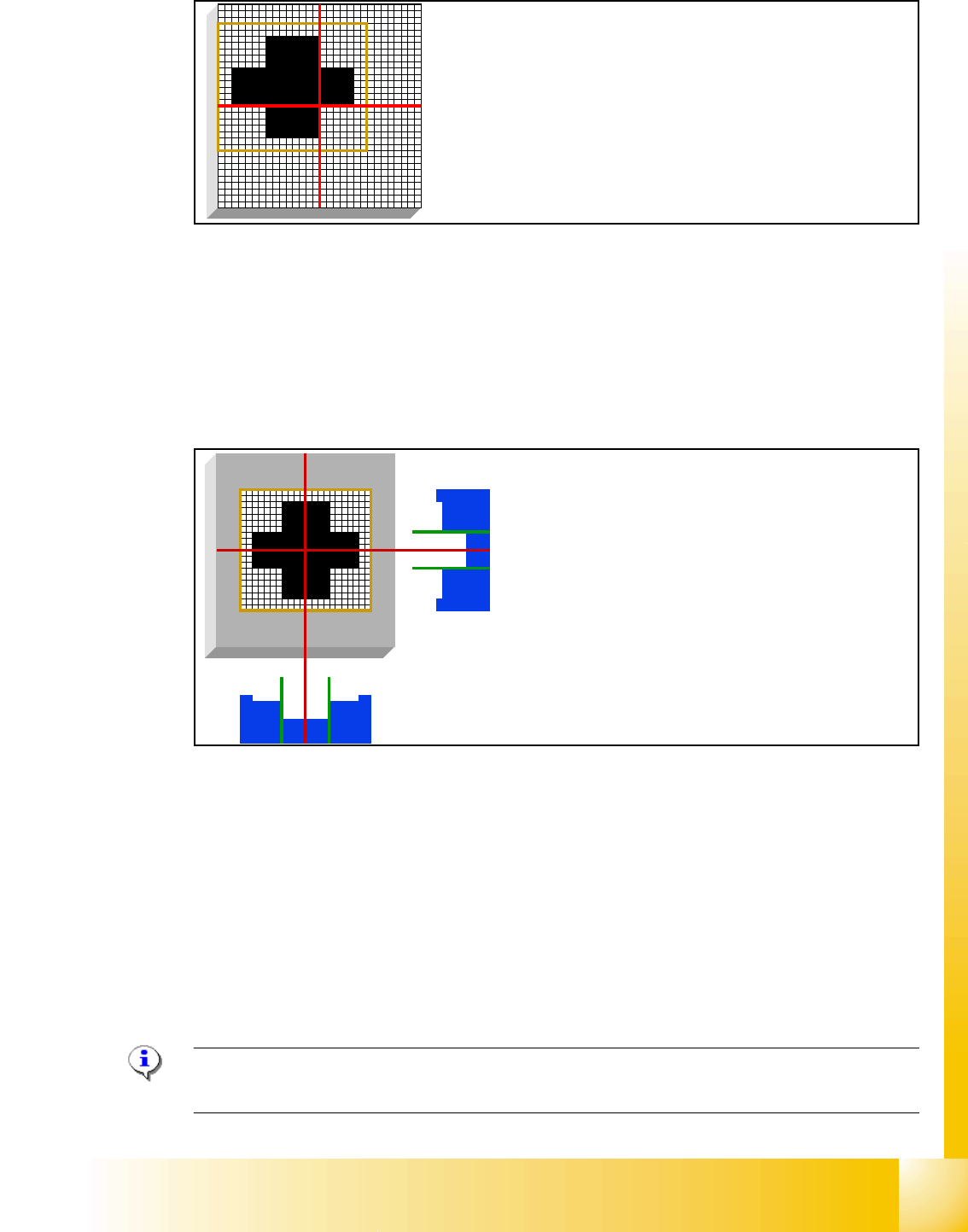
Fig. 5.3 - 3 PCB position recognition run to the PCB nominal position
– PCB position recognition is performed before the first component is picked up.
– The gantry axes move the PCB camera to the theoretical fiducial position. The camera takes
the picture of the first fiducial and the vision system calculates the center position.
5.3.4 PCB Position Recognition - Centering of the PCB Fiducials
Fig. 5.3 - 4 PCB position recognition - centering of the PCB fiducials
– The camera takes the picture of the second fiducial and the vision system calculates the center
position of this picture.
– With both fiducial positions is the board position and board angle calculated.
– All board fiducials are optically centered with this procedure.
– This data is sent to the machine controller
– The correction values are calculated for the X, Y and the angular position of the PCB and the
board internal dilation.
– Now the gantry axes move the placement head to the first pick up position.
PLEASE NOTE: If synthetic fiducials are used, this does not change the described sequence,
although inkspot recognition will now be performed after fiducial recognition. 5
The fiducial is expected at this nominal position. The PCB cam-
era is moved from waiting position to this fiducial position.
The centered fiducial now defines the actual posi-
tion of the board.
1 - 32
Student Guide SIPLACE X
5 Collect&Place-Head 20 Edition 02/2005
32
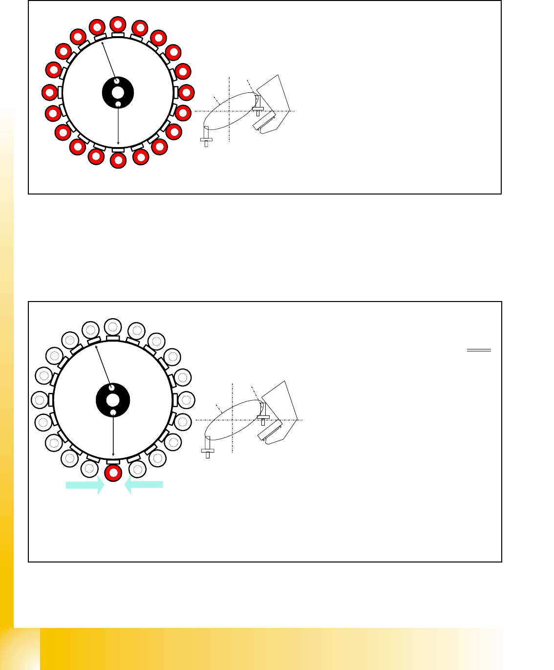
5.3.5 Turning Nozzles 1 to 20 to the Pickup Angle (0° or 90°)
Fig. 5.3 - 5 Turning segments 1 to 20 to the pickup angle (0° or 90°)
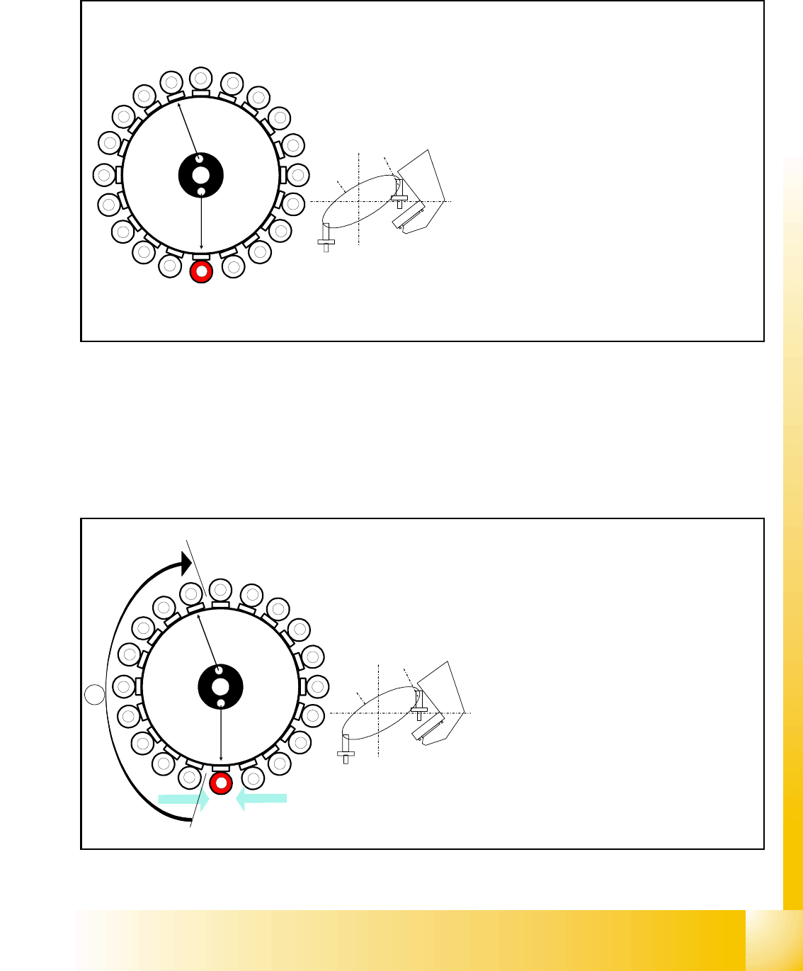
5.3.6 Check Nozzle Length for Component Recognition
Fig. 5.3 - 6 Check nozzle length "component recognition by the component sensor, before pick up"
1
2
3
4
5
6
7
8
9
10
12
11
13
14
15
16
17
18
19
20
Segment 1
Segment 11
S
t
a
r
p
o
s
i
t
i
o
n
CO-Camera
– The segments in the collect & place 20
head are turned
in succession, begin-
ning with segment 1, to the required
pickup angle of 0° or 90°.
– Note: each segment has its own DP drive
1
2
3
4
5
6
7
8
9
10
12
11
13
14
15
16
17
18
19
20
CO- Sensor
CO- Sensor
Segment 1
Segment 11
S
t
a
r
p
o
s
i
t
i
o
n
CO- Camera
Component sensor measures at star
pickup position:
– Vacuum measurement: ’Segment open’
value
–the
component sensor measures the
nozzle length. The measured length be-
fore pickup is verified with the reference
length.
– If a length difference of -0.15mm or +
0.1mm is detected, the gantry axes
move the placement head into the ser-
vice position so that the nozzle can be
replaced.
– Measurement is performed during Z-
movement in the star pickup/placement
position.
1 - 33
Student Guide SIPLACE X
Edition 02/2005 5 Collect&Place-Head 20
33
5.3.7 Picking Up the First Component
Fig. 5.3 - 7 Picking up the first component
The remaining nozzles now pick up the components as the star is stepped and turn these into the
correct centering angle, before they reach the component camera.
5.3.8 Picking Up the 10th Component
Fig. 5.3 - 8 Picking up the 10th component
Star position 0°
– Vision system: no action
– Pick up / placement station: pick up first
component
– Z-axis downwards
– Vacuum check for component pickup
– Component sensor: direct measurement
after picking up the first component (ap-
plies accordingly to all other segments)
– Vacuum check after pickup: check holding
force of the component on the nozzle.
1
2
3
4
5
6
7
8
9
10
12
11
13
14
15
16
17
18
19
20
Segment 1
Segment 11
S
t
a
r
p
o
s
i
t
i
o
n
CO-Camera
10
CO- Sensor
CO- Sensor
Segment 10
Segment 20
S
t
a
r
p
o
s
i
t
i
o
n
CO-Camera
1
2
3
4
5
6
7
8
9
11
12
13
14
15
16
17
18
19
20
A
Star position 162°
– Vision system: prepare SIPLACE Vision
for optical centering.
– Pickup/placement station:
pick up the 10th component
–
A : The components previously picked up
are rotated to the centering angle. (center-
ing angle [0°, 90°, 180°, 270°] = place-
ment angle in 90° steps)
– Measurement of hold circuit for segment 1
(output to measuring sensor)