AL1_SiplaceX-en.pdf - 第218页
1 - 56 S tudent Guide SIPLACE X 5 Collect&Place-Head 20 Edition 02/2005 56
1 - 55
Student Guide SIPLACE X
Edition 02/2005 5 Collect&Place-Head 20
55
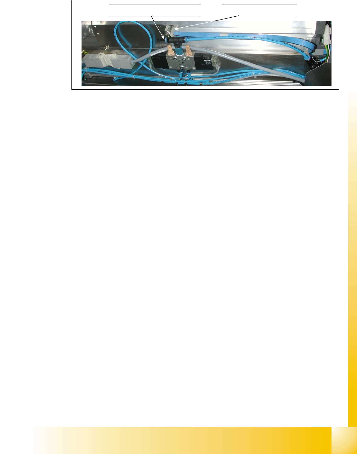
Fig. 5.5 - 5 Air pressure connection of the nozzle changer
The DLM nozzle changers are connected to 2.5 bar (loopedhose in the picture). The C&P20 noz-
zelchanger is connected to 4.5 bar.
CAN- Bus connector of nozzle
changer
Air pressure connection of nozzle changer


Student Guide SIPLACE X
Edition 02/2005 Contents
1
Chapter
Table of Contents
6 Twin-Head . . . . . . . . . . . . . . . . . . . . . . . . . . . . . . . . . . . . . . . . . . . . . . . . . . . . . . . . . 3
6.1 Overview. . . . . . . . . . . . . . . . . . . . . . . . . . . . . . . . . . . . . . . . . . . . . . . . . . . . . . . . . . . . . . . . . . . . . . . 3
6.1.1 Technical Data Twin- Head. . . . . . . . . . . . . . . . . . . . . . . . . . . . . . . . . . . . . . . . . . . . . 4
6.1.2 Parts on the Twin- Head . . . . . . . . . . . . . . . . . . . . . . . . . . . . . . . . . . . . . . . . . . . . . . . 5
6.1.2.1 Vacuum generator Twin- Head. . . . . . . . . . . . . . . . . . . . . . . . . . . . . . . . . . . . . . . 6
6.2 Reference Run Twin-head. . . . . . . . . . . . . . . . . . . . . . . . . . . . . . . . . . . . . . . . . . . . . . . . . . . . . . . . . 7
6.2.1 Reference run at Z axis . . . . . . . . . . . . . . . . . . . . . . . . . . . . . . . . . . . . . . . . . . . . . . . . 8
6.2.2 Reference run at D- axis . . . . . . . . . . . . . . . . . . . . . . . . . . . . . . . . . . . . . . . . . . . . . . . 9
6.2.3 Vacuum check. . . . . . . . . . . . . . . . . . . . . . . . . . . . . . . . . . . . . . . . . . . . . . . . . . . . . . . 9
6.2.4 Height reference run . . . . . . . . . . . . . . . . . . . . . . . . . . . . . . . . . . . . . . . . . . . . . . . . . 10
6.3 Pick up and Placement Cycle of the Twin Head . . . . . . . . . . . . . . . . . . . . . . . . . . . . . . . . . . . . . . 11
6.3.1 General . . . . . . . . . . . . . . . . . . . . . . . . . . . . . . . . . . . . . . . . . . . . . . . . . . . . . . . . . . . 11
6.3.2 Placement principle Twin-head . . . . . . . . . . . . . . . . . . . . . . . . . . . . . . . . . . . . . . . . . 12
6.3.3 Prepare pick up process module 1 . . . . . . . . . . . . . . . . . . . . . . . . . . . . . . . . . . . . . . 12
6.3.3.1 Pick up component module 1. . . . . . . . . . . . . . . . . . . . . . . . . . . . . . . . . . . . . . . 13
6.3.4 Prepare pick up process module 2 . . . . . . . . . . . . . . . . . . . . . . . . . . . . . . . . . . . . . . 14
6.3.4.1 Pick up component module 2. . . . . . . . . . . . . . . . . . . . . . . . . . . . . . . . . . . . . . . 14
6.3.5 Component centering module 1 and 2 . . . . . . . . . . . . . . . . . . . . . . . . . . . . . . . . . . . 15
6.3.6 Prepare placement 1st component . . . . . . . . . . . . . . . . . . . . . . . . . . . . . . . . . . . . . . 16
6.3.6.1 Place 1st component . . . . . . . . . . . . . . . . . . . . . . . . . . . . . . . . . . . . . . . . . . . . . 16
6.3.7 Prepare placement 2nd component . . . . . . . . . . . . . . . . . . . . . . . . . . . . . . . . . . . . . 17
6.3.7.1 Place 2nd component. . . . . . . . . . . . . . . . . . . . . . . . . . . . . . . . . . . . . . . . . . . . . 17
6.4 Adjustments . . . . . . . . . . . . . . . . . . . . . . . . . . . . . . . . . . . . . . . . . . . . . . . . . . . . . . . . . . . . . . . . . . . 19
6.4.1 Description of the boards on the Twin- Head . . . . . . . . . . . . . . . . . . . . . . . . . . . . . . 19
6.4.1.1 Head adapter Twin- Head . . . . . . . . . . . . . . . . . . . . . . . . . . . . . . . . . . . . . . . . . 19
6.4.1.2 Twin- Head main board . . . . . . . . . . . . . . . . . . . . . . . . . . . . . . . . . . . . . . . . . . . 20
6.4.1.3 Vision control board "IC camera" . . . . . . . . . . . . . . . . . . . . . . . . . . . . . . . . . . . . 21
6.4.2 Parameter and Calibrations. . . . . . . . . . . . . . . . . . . . . . . . . . . . . . . . . . . . . . . . . . . . 23
6.4.2.1 Overview calibration steps and parameter in the Sitest . . . . . . . . . . . . . . . . . . . 23
6.4.3 Parameter Twin- Head . . . . . . . . . . . . . . . . . . . . . . . . . . . . . . . . . . . . . . . . . . . . . . . 24
6.4.4 Calibrate D-Axis. . . . . . . . . . . . . . . . . . . . . . . . . . . . . . . . . . . . . . . . . . . . . . . . . . . . . 26
6.4.4.1 Manual Calculation of the ZPC D-axis . . . . . . . . . . . . . . . . . . . . . . . . . . . . . . . . 27
6.4.5 Calibrate head height . . . . . . . . . . . . . . . . . . . . . . . . . . . . . . . . . . . . . . . . . . . . . . . . 27
6.4.6 Zero calibration for pressure regulator on the Twin- Head . . . . . . . . . . . . . . . . . . . . 28
6.4.6.1 Zero calibration vacuum generator. . . . . . . . . . . . . . . . . . . . . . . . . . . . . . . . . . . 28