AL1_SiplaceX-en.pdf - 第267页
1 - 13 S tudent Guide SIPLACE X Ausgabe 02/2005 7 Sit est 13 – Follow the Information an d press the S tart button on the maschine. –P r e s s O K Now the head is calibration the Z- and S tar zer o point correction and s…
1 - 12
Student Guide SIPLACE X
7 Sitest Ausgabe 02/2005
12
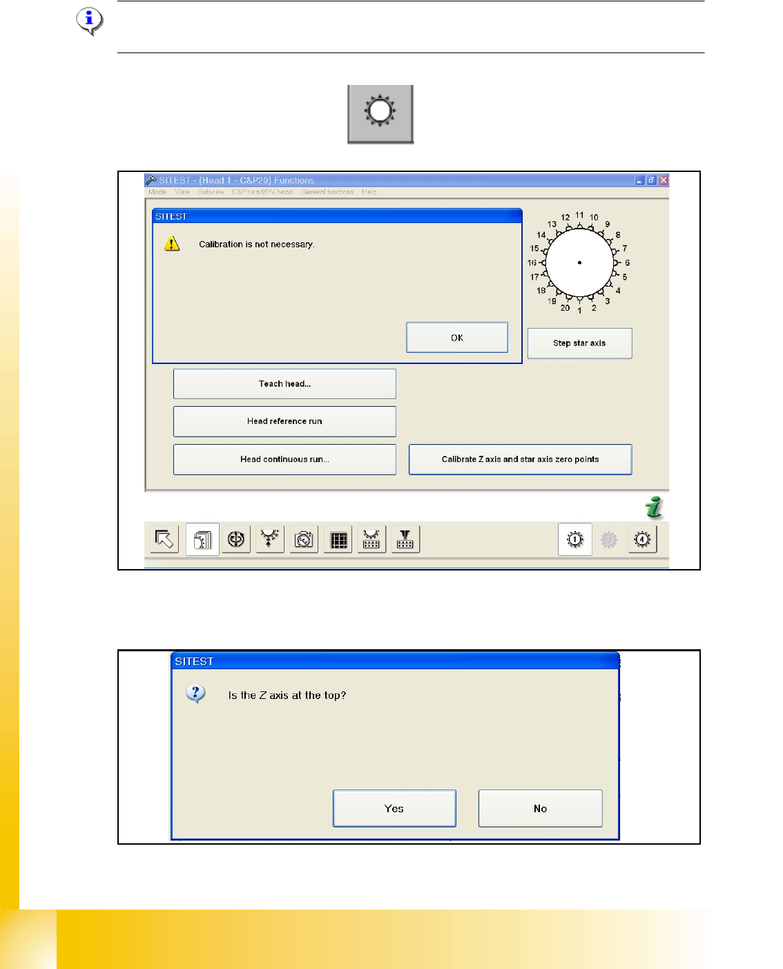
7.2.3 Determination of Z- and Star axes zero point correction (Sitest) :
NOTE : Determination of Z- and star axes zero point correction is only offered if the zpc- values
of the Achs_ver.ma and the EPROM (head) are not the same.
Are the value identical appears the following message:
– Start the Sitest --> Head functions
The values are not identical, you have to calibrate the zero point correction and the following mes-
sage appears:
Check the position of the Z-Axis and press Yes.
1 - 13
Student Guide SIPLACE X
Ausgabe 02/2005 7 Sitest
13
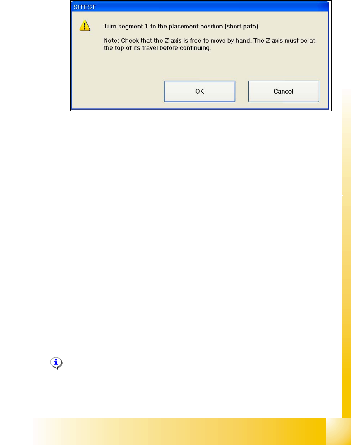
– Follow the Information and press the Start button on the maschine.
–Press OK
Now the head is calibration the Z- and Star zero point correction and save the new values in the
Achs_ver.ma and the Eprom.
Function description: 7
– The Z-Axis move up with the current sensor mode and set the counter to 0.
– Then the Z- axis moves down to 18000 digits until the ball bearing of the Z- axis is between the
raceway of the star axis.
– The star turns left and right and calculated the average value. This is the new zero point cor-
rection (
zpc) value of the star axis.
– The Z- axis moves further down until the ball bearing (Segment) is in the center of the raceway
gap.
– The star turns right into the gap of the raceway and the Z- axis push up the ball bearing against
the raceway. The Z-axis position is read.
– Now the Z- axis position is read on the left side from the raceway gap with the same procedure,
like the right side.
– Afterwards the new zero point correction of the Z- axis is calculated in the following way :
Z- position - diameter ball bearing - thickness of the raceway = new zpc Z- axis
NOTE : The data is directly stored in the Achse_ver.ma and at same time the data is written in the
EPROM of the head.
1 - 14
Student Guide SIPLACE X
7 Sitest Ausgabe 02/2005
14
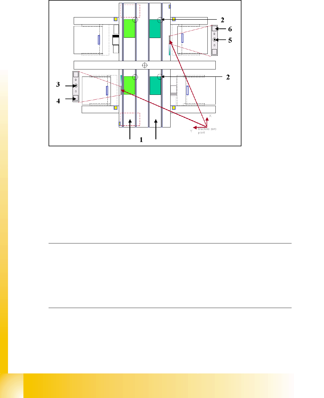
7.2.4 Calibration positions in the machine
Fig. 7.2 - 2 Top view of machine
Key:
(1) Transport direction
(2) Fixed PCB corner BB 1/ 2 Track 1 and 2
(3) Machine zero point BB 1
(4) Calibration position BB 1 (depend on the head type)
(5) Machine zero point BB 2
(6) Calibration position BB 2 (depend on the head type)
Note:
Some calibrations require that you attach nozzles on the placement heads.
Use nozzles of type
956 for C&P6/12, 1235 for C&P20 and for the Twin head 517. Make sure that
all nozzles have been attached correctly, otherwise measuring will lead to incorrect results.
If you need to, place the calibration tool into the "calibration pocket". (Fig. 7.2 - 2).
Before you place the calibration tool, make sure that it is clean. Also, be sure that you insert it into
the "calibration pocket" with its print of the fiducial structure on the bottom. 7