AL1_SiplaceX-en.pdf - 第266页
1 - 12 S tudent Guide SIPLACE X 7 Sitest Ausgabe 02/2005 12 7.2.3 Determination of Z- and St ar axes zero poin t correction (Sitest) : NOTE : Determination of Z- and st ar axes zero point correction is only offered if th…

1 - 11
Student Guide SIPLACE X
Ausgabe 02/2005 7 Sitest
11
7.2.2 Precondition for calibrate the machine
➠ Start SITEST.
➠ Under menu item "Main view", click "Overall reference run", to reference all gantry- and head-
axes.
➠ Configure the nozzle changer and filling level
–
Precondition for calibrate the nozzle changer
C&P head (6/12/20) :
(1) Every magazine of the nozzle changer has to be configured with a nozzle type.
(2) No nozzle on segment 1.
(3) There must be minimum one nozzle present and configured (1) in garage 1 of every magazine.
TWIN- head : (1) Garage 1 of the nozzle changer has to be "empty"
(2) Both nozzles at the TWIN head has to be configured.
NOTE : For C&P12 head it is also possible to configure every magazine "empty" and the head
"full" of nozzles.
➠ Check the zero point correction D-Axis Twin head
➠ Check the zero point correction Z- and Star Axis with the Sitest at the C&P20 head,
if necessary or an error message appears.
1 - 12
Student Guide SIPLACE X
7 Sitest Ausgabe 02/2005
12
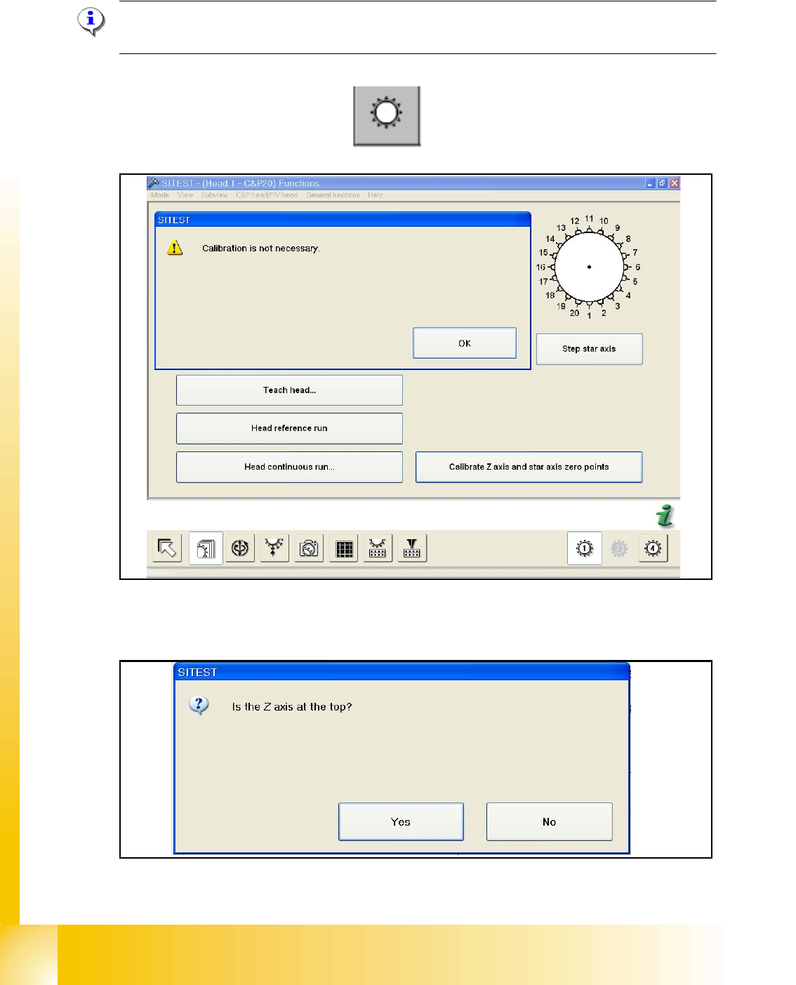
7.2.3 Determination of Z- and Star axes zero point correction (Sitest) :
NOTE : Determination of Z- and star axes zero point correction is only offered if the zpc- values
of the Achs_ver.ma and the EPROM (head) are not the same.
Are the value identical appears the following message:
– Start the Sitest --> Head functions
The values are not identical, you have to calibrate the zero point correction and the following mes-
sage appears:
Check the position of the Z-Axis and press Yes.
1 - 13
Student Guide SIPLACE X
Ausgabe 02/2005 7 Sitest
13
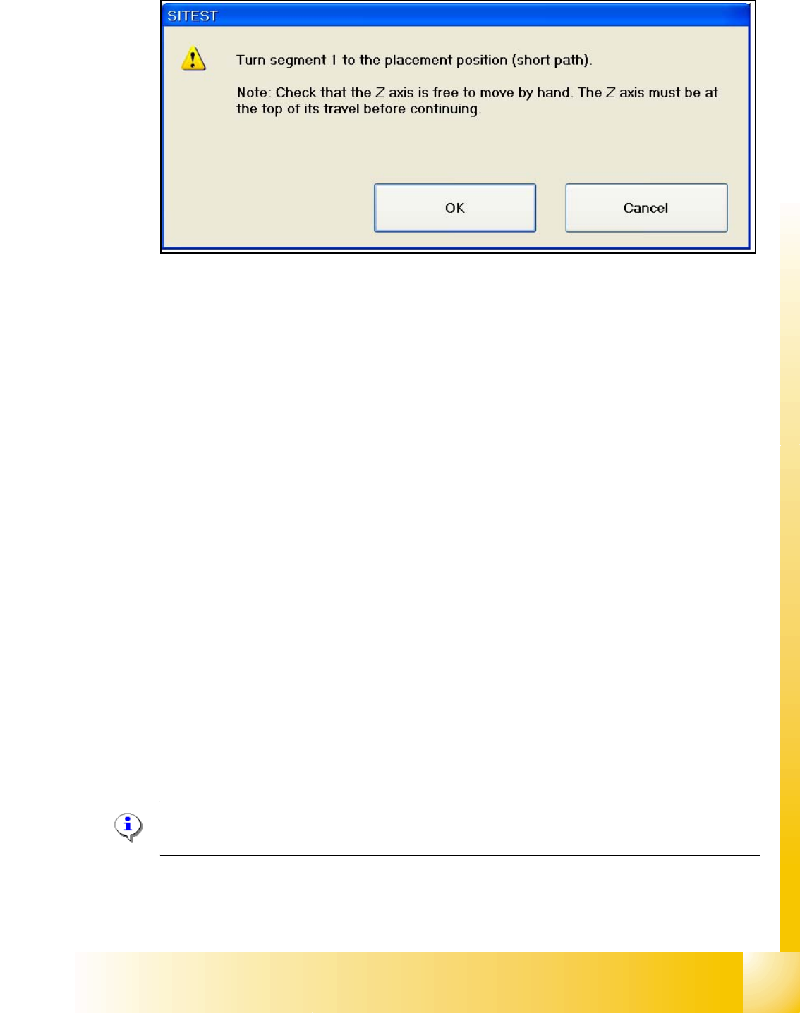
– Follow the Information and press the Start button on the maschine.
–Press OK
Now the head is calibration the Z- and Star zero point correction and save the new values in the
Achs_ver.ma and the Eprom.
Function description: 7
– The Z-Axis move up with the current sensor mode and set the counter to 0.
– Then the Z- axis moves down to 18000 digits until the ball bearing of the Z- axis is between the
raceway of the star axis.
– The star turns left and right and calculated the average value. This is the new zero point cor-
rection (
zpc) value of the star axis.
– The Z- axis moves further down until the ball bearing (Segment) is in the center of the raceway
gap.
– The star turns right into the gap of the raceway and the Z- axis push up the ball bearing against
the raceway. The Z-axis position is read.
– Now the Z- axis position is read on the left side from the raceway gap with the same procedure,
like the right side.
– Afterwards the new zero point correction of the Z- axis is calculated in the following way :
Z- position - diameter ball bearing - thickness of the raceway = new zpc Z- axis
NOTE : The data is directly stored in the Achse_ver.ma and at same time the data is written in the
EPROM of the head.