AL1_SiplaceX-en.pdf - 第255页
S tudent Guide SIPLACE X -Series Edition 02/2005 Contents 1 Chapter T able of Content s 7 Sitest . . . . . . . . . . . . . . . . . . . . . . . . . . . . . . . . . . . . . . . . . . . . . . . . . . . . . . . . . . . . . 3…
1 - 36
Student Guide SIPLACE X
6 Twin-Head Edition 02/2005
36
6.5.2.3 Description of the functions
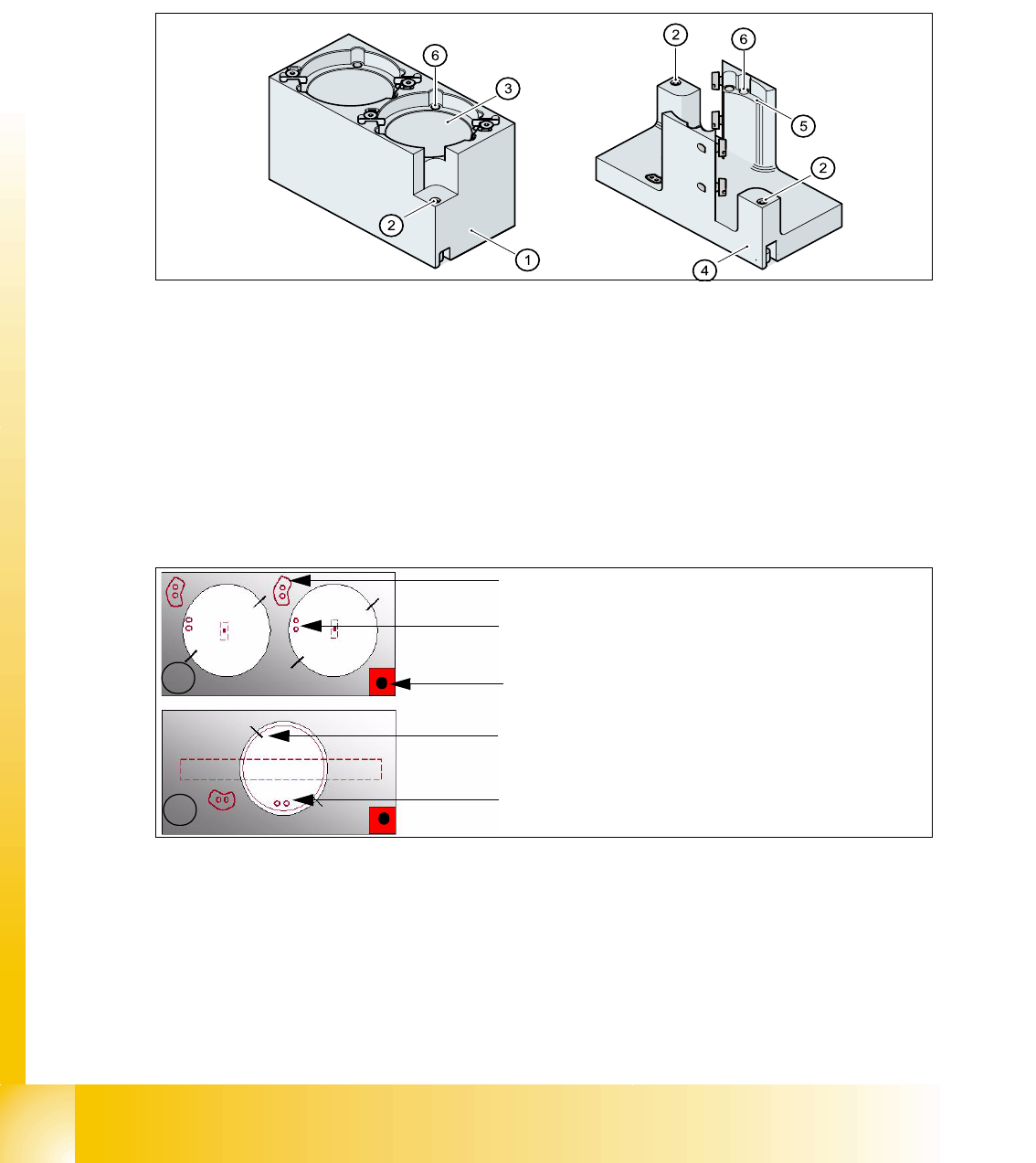
The magazine for standard nozzles has 1 positioning fiducial for position detection, while the mag-
azine for special nozzles/grippers has two positioning fiducials. The nozzles are fixed by balls in
the holder. They are then either locked for return or released for pick up, depending on the direc-
tion of rotation of the DP axis.
Fig. 6.5 - 4 Magazine for standard- and special nozzles
Legend
Position of the nozzle in the magazines 6
(1) Standard magazine (2) Positioning fiducia
(3) Nozzle holder (4) Magazine for special nozzles
(5) Nozzle holder (6) Balls for lifting the nozzles
1
2
- Description of the index pins for the right
position of the nozzle in the magazine.
- Position of the nozzle with the holes for the
index pins. (pick up angle 184 degree)
- Fiducial for calibration, serves for the position
determination of the magazine.
- centering pins for the nozzles
- The magazines for the special nozzles are
turned 90° degree pick up angle 275°.

Student Guide SIPLACE X -Series
Edition 02/2005 Contents
1
Chapter
Table of Contents
7 Sitest . . . . . . . . . . . . . . . . . . . . . . . . . . . . . . . . . . . . . . . . . . . . . . . . . . . . . . . . . . . . . 3
7.1 Overview SITEST . . . . . . . . . . . . . . . . . . . . . . . . . . . . . . . . . . . . . . . . . . . . . . . . . . . . . . . . . . . . . . . . 3
7.1.1 Starting/Terminating the Test Program . . . . . . . . . . . . . . . . . . . . . . . . . . . . . . . . . . . . 3
7.1.1.1 Starting. . . . . . . . . . . . . . . . . . . . . . . . . . . . . . . . . . . . . . . . . . . . . . . . . . . . . . . . . 3
7.1.1.2 Terminating . . . . . . . . . . . . . . . . . . . . . . . . . . . . . . . . . . . . . . . . . . . . . . . . . . . . . 4
7.1.2 Main view Sitest. . . . . . . . . . . . . . . . . . . . . . . . . . . . . . . . . . . . . . . . . . . . . . . . . . . . . . 5
7.1.3 Icons in the main view and their sub menus . . . . . . . . . . . . . . . . . . . . . . . . . . . . . . . . 6
7.2 Calibration . . . . . . . . . . . . . . . . . . . . . . . . . . . . . . . . . . . . . . . . . . . . . . . . . . . . . . . . . . . . . . . . . . . . . 9
7.2.1 Calibration in general. . . . . . . . . . . . . . . . . . . . . . . . . . . . . . . . . . . . . . . . . . . . . . . . . 10
7.2.2 Precondition for calibrate the machine . . . . . . . . . . . . . . . . . . . . . . . . . . . . . . . . . . . 11
7.2.3 Determination of Z- and Star axes zero point correction (Sitest) :. . . . . . . . . . . . . . . 12
7.2.4 Calibration positions in the machine . . . . . . . . . . . . . . . . . . . . . . . . . . . . . . . . . . . . . 14
7.2.5 Operation for calibrating the entire machine . . . . . . . . . . . . . . . . . . . . . . . . . . . . . . . 15
7.2.6 ALL heads and cameras . . . . . . . . . . . . . . . . . . . . . . . . . . . . . . . . . . . . . . . . . . . . . . 16
7.2.6.1 C&P head. . . . . . . . . . . . . . . . . . . . . . . . . . . . . . . . . . . . . . . . . . . . . . . . . . . . . . 17
7.2.6.2 Twin head. . . . . . . . . . . . . . . . . . . . . . . . . . . . . . . . . . . . . . . . . . . . . . . . . . . . . . 18
7.2.7 Calibrate the conveyor edges . . . . . . . . . . . . . . . . . . . . . . . . . . . . . . . . . . . . . . . . . . 19
7.2.8 Calibrate the conveyor widths . . . . . . . . . . . . . . . . . . . . . . . . . . . . . . . . . . . . . . . . . . 19
7.2.9 Calibrate the PCB reference corner . . . . . . . . . . . . . . . . . . . . . . . . . . . . . . . . . . . . . 20
7.2.10 Calibrate the Pick up position . . . . . . . . . . . . . . . . . . . . . . . . . . . . . . . . . . . . . . . . . 21
7.2.11 LP- Mapping . . . . . . . . . . . . . . . . . . . . . . . . . . . . . . . . . . . . . . . . . . . . . . . . . . . . . . 22
7.2.12 Head- Mapping . . . . . . . . . . . . . . . . . . . . . . . . . . . . . . . . . . . . . . . . . . . . . . . . . . . . 22
7.2.13 Basically description of all calibration steps . . . . . . . . . . . . . . . . . . . . . . . . . . . . . . 23
7.2.14 Calibrate and teach machine positions . . . . . . . . . . . . . . . . . . . . . . . . . . . . . . . . . . 28
7.2.14.1 Conveyor edges (Conveyor rails). . . . . . . . . . . . . . . . . . . . . . . . . . . . . . . . . . . 28
7.2.14.2 Conveyor width calibration . . . . . . . . . . . . . . . . . . . . . . . . . . . . . . . . . . . . . . . . 28
7.2.14.3 PCB reference corner. . . . . . . . . . . . . . . . . . . . . . . . . . . . . . . . . . . . . . . . . . . . 28
7.2.14.4 Pick up position (Calibrate the component table Track 1- 90) . . . . . . . . . . . . . 29
7.2.14.5 Pick up position (Calibrate the X- tables Track 1- 40) . . . . . . . . . . . . . . . . . . . 29
7.2.15 PCB mapping . . . . . . . . . . . . . . . . . . . . . . . . . . . . . . . . . . . . . . . . . . . . . . . . . . . . . 30
7.2.16 Head mapping( C&P,Twin head). . . . . . . . . . . . . . . . . . . . . . . . . . . . . . . . . . . . . . . 31
7.2.17 New function in the Sitest program . . . . . . . . . . . . . . . . . . . . . . . . . . . . . . . . . . . . . 32
7.2.17.1 Menu of transport . . . . . . . . . . . . . . . . . . . . . . . . . . . . . . . . . . . . . . . . . . . . . . . 32
7.2.17.2 Function Firmware download. . . . . . . . . . . . . . . . . . . . . . . . . . . . . . . . . . . . . . 33
7.2.17.3 Head modularity Siplace X. . . . . . . . . . . . . . . . . . . . . . . . . . . . . . . . . . . . . . . . 34

1 - 2
Student Guide SIPLACE X -Series
Contents Edition 02/2005
2