AL1_SiplaceX-en.pdf - 第214页
1 - 52 S tudent Guide SIPLACE X 5 Collect&Place-Head 20 Edition 02/2005 52 5.5.2 Det ail view of nozzle changer 20 segment C&P- head Fig. 5.5 - 2 Detail view of nozzle changer 20 segment C&P head Legend lef t…
1 - 51
Student Guide SIPLACE X
Edition 02/2005 5 Collect&Place-Head 20
51
5.5 Nozzle changer
The Siplace X is supplied with 6 segment -, 12 segment- or 20 segment Collect&Place heads. As
an option, nozzle changer can be installed for each collect&place head type. This enables the noz-
zle configuration to be changed quickly, thus allowing the collect&place head to be quickly
adapted to the needs of the placement process. The nozzle changer configuration for C&P20
looks as follows.
5.5.1 Nozzle changer for 20 segment C&P head
The nozzle changer consists of six magazines, each with twelve nozzle garages (see Fig. 8.5 -
2),how the individual garages freely are configurable. Every magazine is clampt on the basic body
with 4 push buttons. The magazine can be removed by the activity one for tipping over lever (per
magazine of one).The magazines are seated on a common support and each magazine is cen-
tered using two parallel pins and another pin is used to move the magazine shutter. A visual report
(green LED) shows, with the help of the built-in microswitches, whether all magazines are locked
correctly at the nozzle changer carrier.
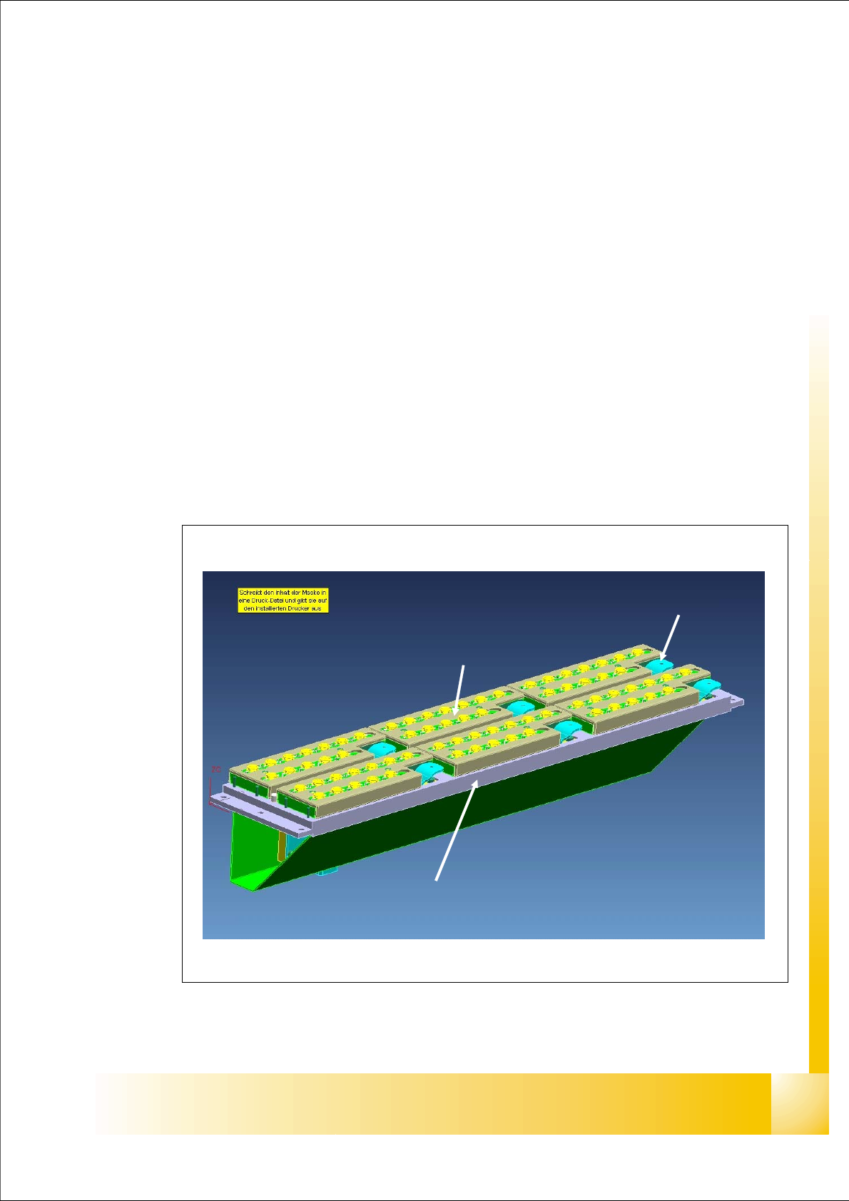
Fig. 5.5 - 1 main view - nozzle changer and nozzle magazin 20 segment C&P head
tipping over lever to remove the
magazine
nozzle changer basic body
magazine
1 - 52
Student Guide SIPLACE X
5 Collect&Place-Head 20 Edition 02/2005
52
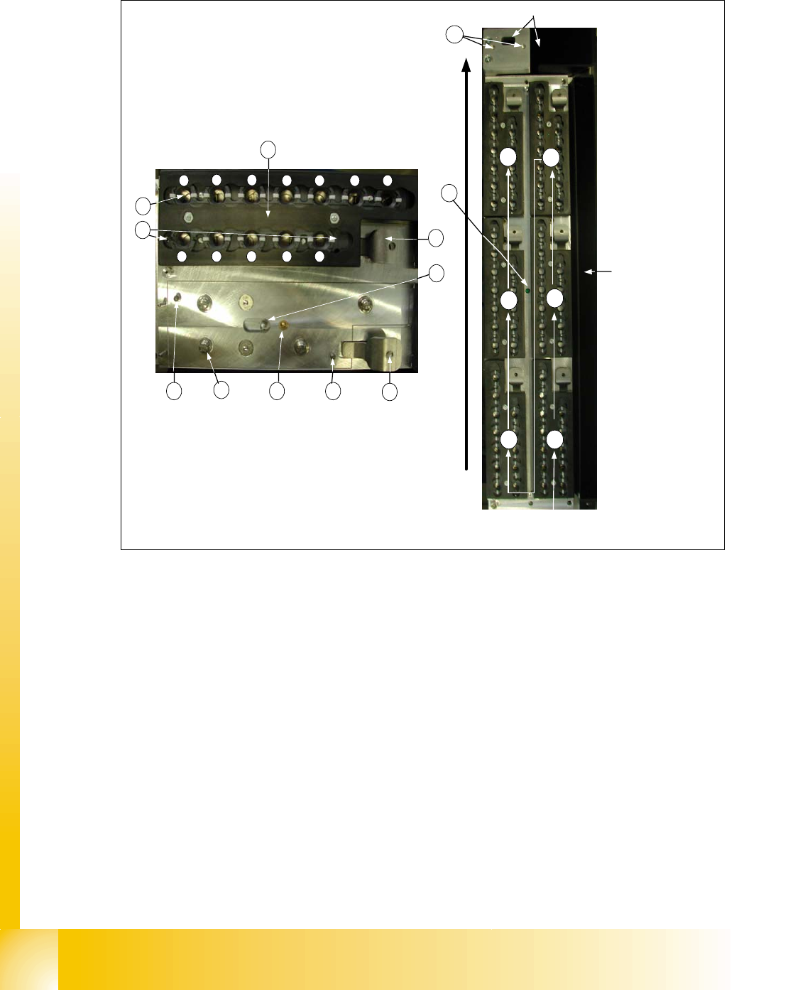
5.5.2 Detail view of nozzle changer 20 segment C&P- head
Fig. 5.5 - 2 Detail view of nozzle changer 20 segment C&P head
Legend left picture in Fig.8.5-2
(1) X/Y position of calibration fiducial (2) Locking plate
(3) Nozzle garage (4) The parallel pins to the centering maga-
zine
(5) Microswitch for magazine recognition (6) Tipping over lever to remove the magazine
(7) Locking Pin of magazine (8) 4 push button to the mount on the nozzle
changer carrier
(9) green LED check for a right mount of all
magazines on the nozzle changer carrier
(10) X/Y position of calibration fiducial of
nozzle reject box
conveyor direction
1
2
3
4
5
6
way of counting of the
magazines
nozzle reject box
component reject box
1
2 3
4 5 6 7
8 9 10 11 12
4
8
5 4
6
7
6
2
3
1
9
10
1 - 53
Student Guide SIPLACE X
Edition 02/2005 5 Collect&Place-Head 20
53
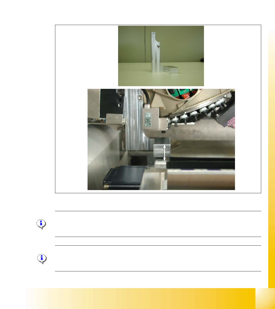
5.5.3 Assembly with adjusting tool of nozzle changer 20 segment C&P- head
So that the safe distance gets large sufficiently between head and nozzle changer and this one
strained himself isn't exhausted by the machine tolerances, the edition of the nozzle changer, the
so-called docking unit is adjusted to 20 mm +/-0,2mm by means of a teaching to the head. The
adjustment tool will be placed at the position of the pressure control valve. The pressure control
valve has to be unscrewed (not removed). Now it is possible to put on the adjusting tool without
any problems. The support of the nozzle changer carrier has to be adjusted with washers in its
height until the the nominal distance is acchieved and then it has to be fixed.
Fig. 5.5 - 3 Assembly with adjusting tool of nozzle changer at C&P20- head (part no. 03035130-0x)
Please Note for assembling the nozzle changer :
During assembling the nozzle changer keep attention that the component reject box can be easily
removed. Don´t use to long screws, otherwise the component reject box will be fixed.
Please Note for assembling the adjusting tool:
During assembling the adjustment tool keep attention that this will be done between transport and
component table. Otherwise it is not possible to put the head beyond the transport .
20mm +/- 0,2mm