AL1_SiplaceX-en.pdf - 第299页
1 - 9 S tudent Guide SIPLACE X Edition 02/2005 8 Siplace Vision 9 The camera moves to the progra mmed bad mark co ordinates. The dimension of the evaluatio n area have to be programme d only one time. Fig. 8.1 - 2 T rian…
1 - 8
Student Guide SIPLACE X
8 Siplace Vision Edition 02/2005
8
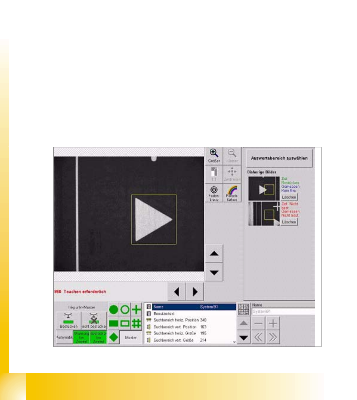
8.1.9 Pattern for bad marks
Other shapes and structures are taught for the positive and negative case. All taught pictures are
shown with their results in a separate area.
The teaching is done in 2 steps before starting of the placement:
First the positive bad mark is taught on the PCB and than the negative bad mark is taught, possibly
on another board.
These bad mark have 3 areas:
=> positive bad mark for the placement
=> negative bad mark for skipping placement
=> in doubt - if the bad mark could not be assigned e.g. the bad mark was not correctly strike out -.
=> Select after teaching the ‚Automatic- Button'.
Function and sequence of the 2D Bad Mark teaching:
=> select the teaching bad mark from fiducial list
=> put PCB (with different bad marks) into input conveyor press 'center fiducial' button and the
PCB is transported in processing area and clamped the gantry move to fiducial 1 position.
=> teach the respective 'positive' or 'negative' bad mark with the menu 'Geometry'.
=> move to the other kind of bad mark with 'next fiducial' button.
=> teach this bad mark with he same evaluation area.
=> to finish the Teach procedure press Button 'Automatic'. (see Fig. 12.2-2 at left bottom)
Fig. 8.1 - 1 Triangle teached as a bad mark (positiove for placement)
1 - 9
Student Guide SIPLACE X
Edition 02/2005 8 Siplace Vision
9
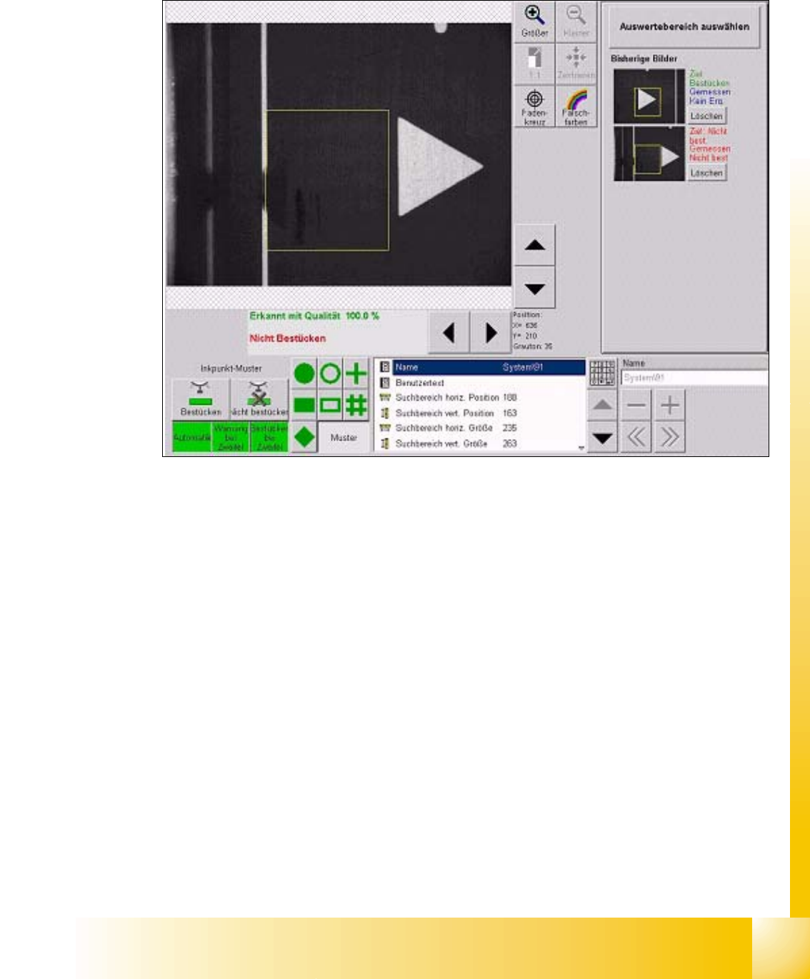
The camera moves to the programmed bad mark coordinates. The dimension of the evaluation
area have to be programmed only one time.
Fig. 8.1 - 2 Triangle teached as a bad mark (negative to skip placement)
For the negative bad mark move the camera above another fiducial or:
teach camera manual to the position of the sticker; or:
mark the positive bad mark respective.
1 - 10
Student Guide SIPLACE X
8 Siplace Vision Edition 02/2005
10
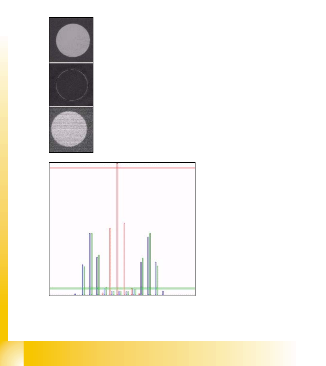
8.1.9.1 The histogram method
Each of the teach picture is brightness normed a middled histogram is determined. The model
consists on a histogram for positive respective negative case. At the classification is the histogram
of the evaluation of the actual picture calculated and deviation to the histograms of the pos. /neg.
model is determined. The picture histogram is assigned to the class where the smallest difference
is.
Following show the process with an example:
Teach picture "placement": bright circle on dark background.
Teach picture "no placement": fiducial is colored with black 'Edding'
Picture to classify
red length bar: teached histogram
"no placement"
green length bar: teached histogram
"placement"
blue length bar: actual histogram of
the evaluation picture
cross bar: distance to teach-histo-
gram.
here has the blue histogram a low dis-
tance to the green bar --> "place"