AL1_SiplaceX-en.pdf - 第296页
1 - 6 S tudent Guide SIPLACE X 8 Siplace Vision Edition 02/2005 6 8.1.5 Synthetic fiducials In rough se arch step is with reduce d resolution th e gray va lue difference betwe en both po ints of a point pair de termined.…

1 - 5
Student Guide SIPLACE X
Edition 02/2005 8 Siplace Vision
5
8.1.4 Shape of fiducials for PCB position and placement position recognition
Following 7 (9) shapes of fiducial could be taught as a synthetic fiducial.
Following measuring results of the fiducial issued:
Kind of fiducial (naming in fiducial
list) What to teach / comment
Cross; Double cross; Shape, dimension, stroke thickness and bright or dark picture.
Circle Shape, dimension and bright or dark picture..
Circle ring Shape, dimension, stroke thickness and bright or dark picture.
Rectangle or square (square a special
form of a rectangle)
Shape, dimension and bright or dark picture.The square is a well-known
special case of the rectangle where all sides are adjusted to identical
values.
Rectangular ring or squared ring(squared
ring a special form of a rectangle ring)
Shape, dimension, stroke thickness and bright or dark picture.The
squared ring is a well-known special case of the rectangular ring where
all sides are adjusted to identical values.
'Diamond' - a 45° turned square Shape, dimension and bright or dark picture.
'Pattern' other fiducial shapes 2D (trian-
gle, circle segment, conductive pattern or
similar structures)
Pattern recognition algorithm, the fiducial is as a - '2 D-fiducial' - in the
fiducial list named.
At fiducial teaching: At fiducial centering:
=> X-position of the structure to camera center => X-position of the structure to camera center
=> Y-position of the structure to camera center => Y-position of the structure to camera center
=> Angle deviation of the structure to PCB-camera
coordinate system
1 - 6
Student Guide SIPLACE X
8 Siplace Vision Edition 02/2005
6
8.1.5 Synthetic fiducials
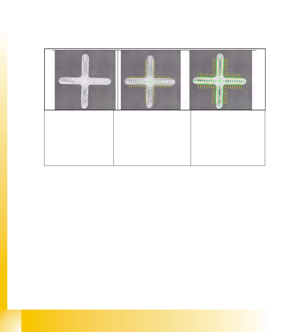
In rough search step is with reduced resolution the gray value difference between both points of
a point pair determined. The shape position of the point pair calculates the algorithm from the geo-
metric model.
From the gray value difference the real position is determined.
In fine search step is along the scanning lines the largest gray value difference determined. From
this positions is the regression line calculated their position define the fiducial center position. The
positions of the scanning lines are defined from the point pair positions of the rough search. Par-
allel to the position measurement is a quality value determined. This quality value show how ac-
curate fit the theoretical model at the determined fiducial position.
This principal could be used for bad mark recognition too. The negative bad mark is recognized if
the quality level is lower than a defined limit.
Camera picture of the
fiducial
Rough search with reduced
resolution:
Position of the
scanning lines (yellow) at rec-
ognized pairs.The blue point
has a higher gray value
(brighter) than the yellow one.
Fine search: Position of the
scanning lines (yellow) at
recognized pairs.
Green crosses: found posi-
tions of the largest gray gra-
dient along the Scanning line
Green straight line: regres-
sion line
1 - 7
Student Guide SIPLACE X
Edition 02/2005 8 Siplace Vision
7
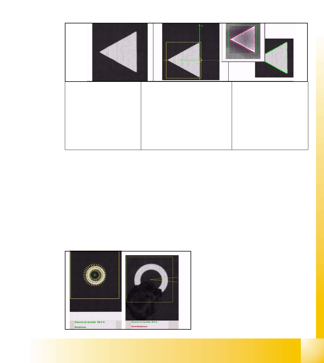
8.1.6 Pattern as fiducials
Learn patterns with an automatic algorithm for 2D fiducial:
=> first is the search area the so-called Region Of Interest ROI defined.
=> the reference point of the pattern have to be calculated (recommended) or manual selected
(more imprecise with this manual definition). (This is the point where the placement refers to).
=> the pattern is calculated to determine the reference point.
=> test pattern on reliability using a few different individual fiducials (stability of measuring results).
The precision of the Reference point defines the placement accuracy later. Best is to determine
the reference point automatically and check it.
8.1.7 Bad mark recognition
Bad mark recognition could be programmed on following different ways.
8.1.8 Synthetic bad mark
There are 9 different synthetic shapes offered for synthetic bad mark. Similar teaching fiducials:
the shape, the dimension and the optical impression - bright or dark - of the 'positive bad mark'
have to be taught. Is the shape recognized the positive bad mark for placement is recognized. Is
the shape in search area not recognized is a negative bad mark recognized (no time waste at
missing structure) and no placement is done respective as a global bad mark the local bad mark
of the single circuits are measured. (See 4.1.1)
This -left- picture shows the fine search of the
synthetic Bad Mark teachings with result.
This -right- picture is the result of the negative
marked bad mark.
Camera picture of trian-
gle fiducial
Defined reference point:The
reference point of a fiducial
defines the placement positions.
Therefore this has to be as pre-
cise as possible because the
basic coordinates of the PCB-
position are set here. -Here the
position with the largest bright-
ness difference was selected -.
Learned pattern:
Referring to the reference
point learn the system the
shape of pattern and save
this outline as 'Teach pic-
ture'.