AL1_SiplaceX-en.pdf - 第144页
1 - 54 S tudent Guide SIPLACE X 4 Collect &Place-He ad 6/12 Edition 02/2005 54 Description LED‘s on the head adapter: 4 – H6 -LZOS Light barrier Z-axis upper stop – H5 -LZUS Lig ht barrier Z-ax is down position – H4 …
1 - 53
Student Guide SIPLACE X
Edition 02/2005 4 Collect &Place-Head 6/12
53
4.4 Adjustments
4.4.1 Description of the PCB boards on the 6/12 C&P head
All described adjustments in this chapter are head spezific and are necessary here for the
6/12 C&P head.
4.4.1.1 Headadapter for 6/12 C&P head
At the head modularity we can use the same head adapter for the 6 and 12 segment C&P heads.
The head adapter must be exchanged if you mounting the Twin head or the C&P 20 head.
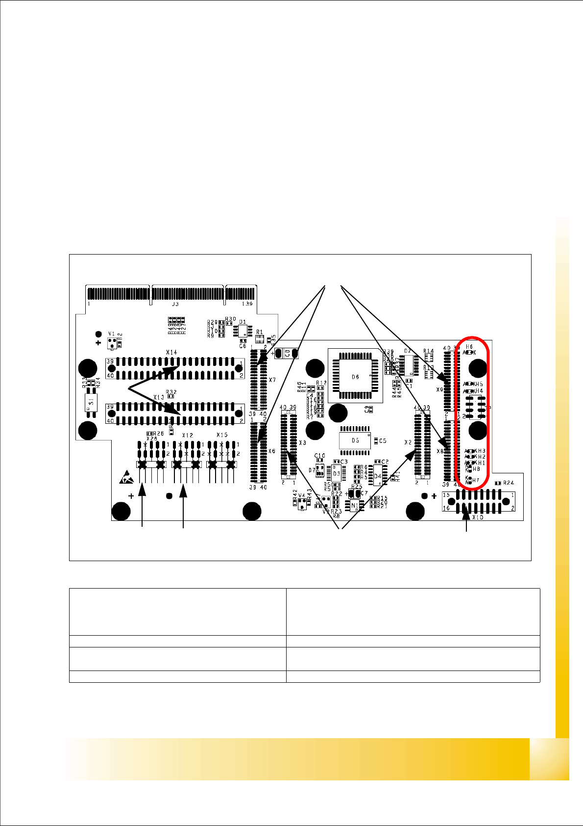
Fig. 4.4 - 1 Headadapter for 6/12 C&P head(03019066-0x)
1
2
45
3
6
7
LED‘S
(1)X6 -X9 Connector for CAN Prozessor-board’
80C515C 8Bit not mounted, because these
function make the 16 Bit processor on the head
interface C500.
(2)X2/X3 Connector for the stepping motor board
(3)X10 Connector vacuum board (4) X12 Dp station (motor, track signale)
(5)X26 Option component sensor (6)X13/14 connector for the flat cable to the intermedi-
ate distribution boardr
(7)Connector to the headinterface C500 (8)
1 - 54
Student Guide SIPLACE X
4 Collect &Place-Head 6/12 Edition 02/2005
54
Description LED‘s on the head adapter: 4
– H6 -LZOS Light barrier Z-axis upper stop
– H5 -LZUS Light barrier Z-axis down position
– H4 -LSM Stepper motor board not connected
– H3 -LSZD Light barrier Swivel in for turning at DP-station
– H2 -LSVZ Light barrier Vacuum / air kiss Z-axis
– H1 -LSVA Light barrier Vacuum / air kiss reject position
– H8 -P15_F 15V Power supply
– H7 -C167
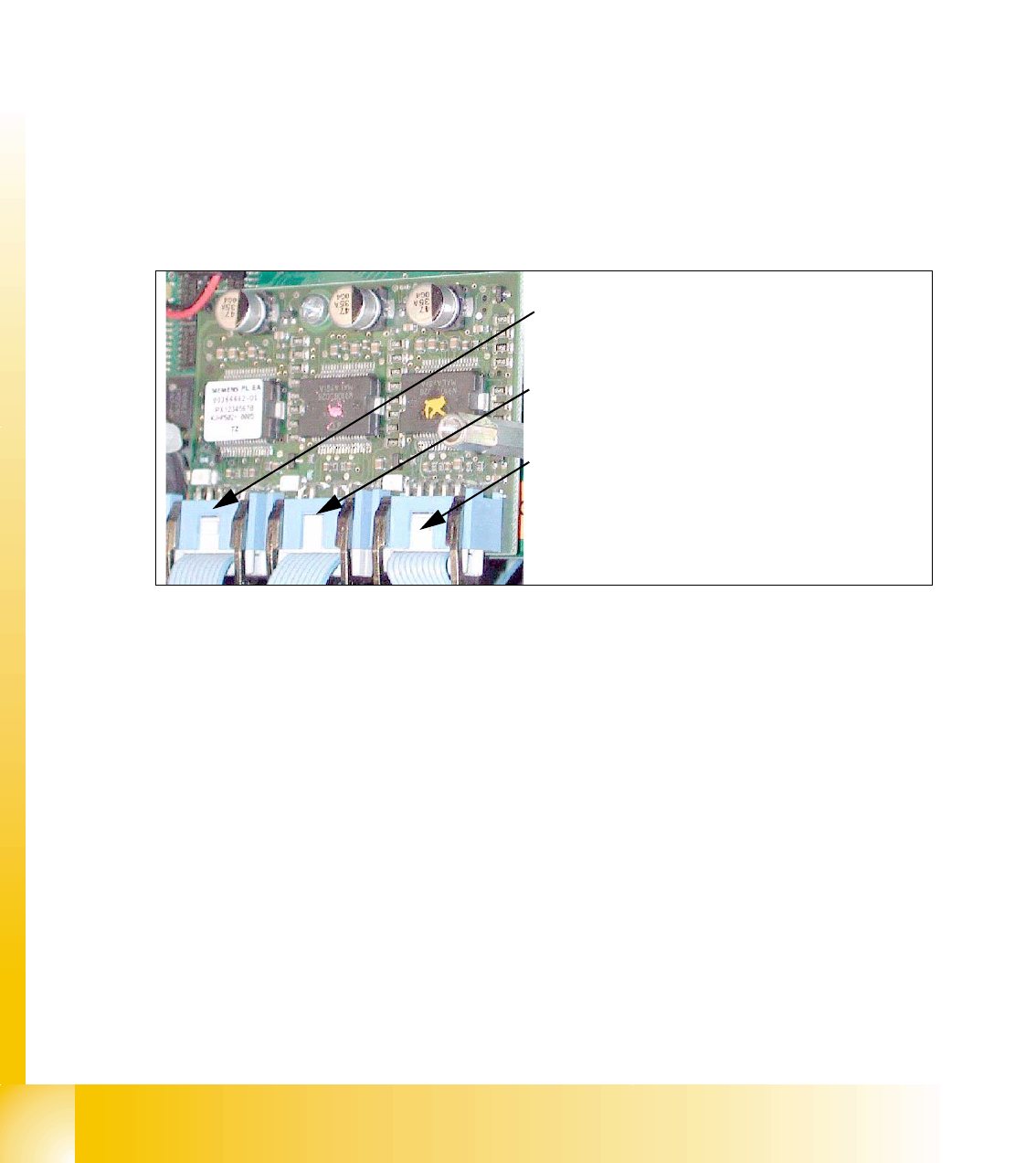
4.4.1.2 Stepping motor board
The stepping motor board for the valve drivers and the swivel function on the DP station is moun-
ted onto the head adapter. Now, the functions are controlled via the 16 Bit processor board on the
head interface.
Fig. 4.4 - 2 Stepping motor board
2
3
1
Stepping motor rejectposition
(for X3/X2. X4 and HF-machine)
Stepping motor pick up-, placement-
(and reject position HF/HF3)
Stepping motor DP-axis
1 - 55
Student Guide SIPLACE X
Edition 02/2005 4 Collect &Place-Head 6/12
55
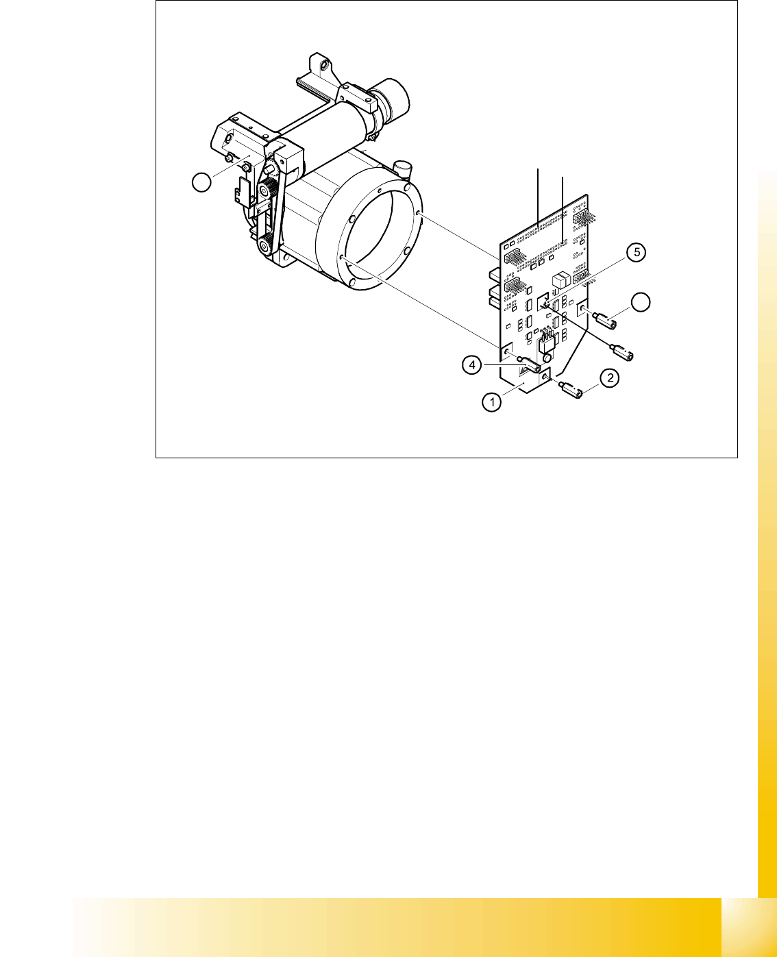
4.4.1.3 SP_12 Digital intermediate distribution board (00330648-05)
4
Fig. 4.4 - 3 SP6_12 intermediate distribution board (Picture DLM 1)
Legend
The intermediate distribution board (1) is fixed to the front part (4) with four spacer bolts (items 2,
3,4 and 5). The cover of the intermediate distribution board is fixed with push buttons.
4
Two 40-pin ribbon cables run from plug X1 and X2 on the intermediate distribution board to socket
X14 / X13 on the head board.
(1) Intermediate distribution board (2) M3x10 spacer bolt
(3) M3x10 spacer bolt (4) M3x10 spacer bolt
(5) M3x10 spacer bol (6) Front part of the collect&place head
3
6
X 1
X 2