AL1_SiplaceX-en.pdf - 第77页
1 - 7 S tudent Guide SIPLACE X Edition 02/2005 3 Gantry 7 3.2 Reference run Gantry 3.2.1 Sequence reference run at X- and Y -axis Fig. 3.2 - 1 Sequence Reference run X_Y – Both axis are started at th e same ti me. A c hs…
1 - 6
Student Guide SIPLACE X
3 Gantry Edition 02/2005
6
Description: 3
The head mounting plate with the C&P head or TWIN-head is moved via the linear guidance which
are mounted over the secondary part of the linear motor and under the secondary part of the linear
motor in X direction. The Y- axis moves the entire X-axis with the C&P or TWIN-head.
For X and Y position recognition we use incremental metal scales. They are positioned over the
secondary part of the X - Linear motor and under the secondary part of the Y- Linear motor. A cor-
responding incremental encoder reads the increments from the metal scales and generates track
signals as a result. The encoder transmits the track signals to the axis control card, which uses
the track signals to determine axis position and to control the motor.
Left and right of every incremental scale are mounted the metal actuators for the BERO´s. The
BERO‘s on the X- and Y- axes are required for the reference run, the velocity check and the
hardware limit switch.
Additionally each axis has a mechanical end stop (elastomer bumper).
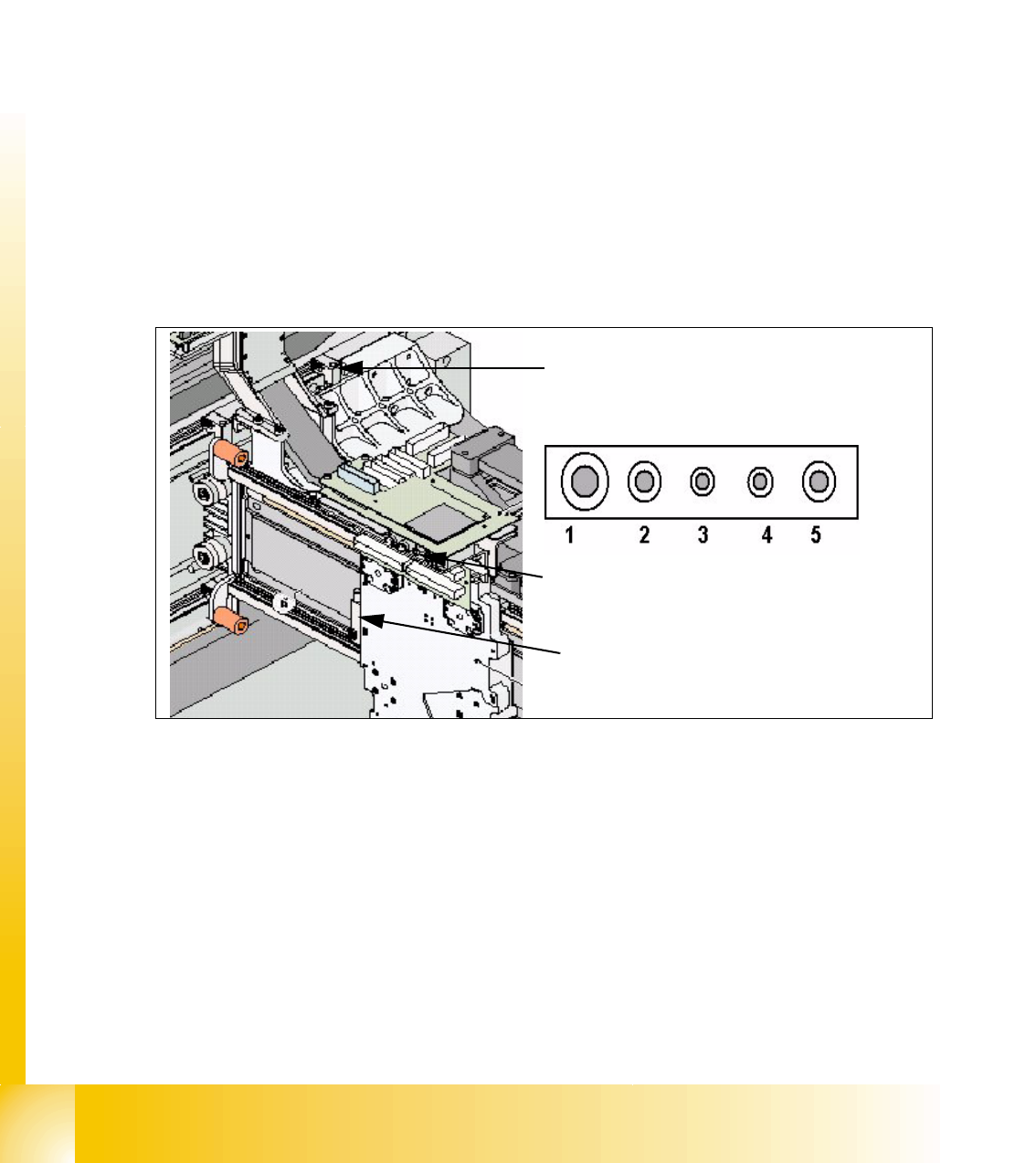
3.1.2 Pneumatic connectors on the gantry
Fig. 3.1 - 4 Pneumatic connectors on the gantry
Pneumatic connectors Legend
– Cooling the Y- axes occurs via a motor which generate compressed air it is mounted in the
pneumatic unit.
– The X axes are cooled from the C&P head or Twin head with exhaust of the vacuum system.
(1) Holding circuit C&P6/12/20 head (2) C&P6/12 head pick up circuit an air kiss
(2) Twin head Segment 1 vacuum generator (3) Twin head Segment 1 retract unit
(4) Twin head Segment 2 / C&P20 retract unit (5) Twin head Segment 2 / C&P20 Vacuum
generator
Pneumatic connector for cooling the Y-Linear
motor
Pneumatic connectors under the Head interface.
Pneumatic connector for cooling the X-Linear
motor
1 - 7
Student Guide SIPLACE X
Edition 02/2005 3 Gantry
7
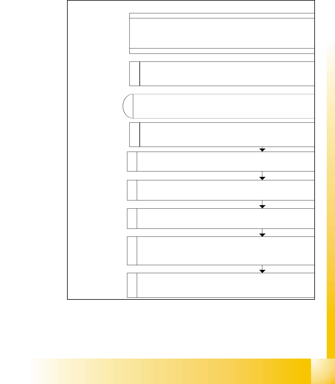
3.2 Reference run Gantry
3.2.1 Sequence reference run at X- and Y-axis
Fig. 3.2 - 1 Sequence Reference run X_Y
– Both axis are started at the same time.
Achsen verfahren
z
Referenzpunkt-Sch
Schaltpunkt 1 bis
Fahrrichtung der Achse
Endesignal für Referen
Voraussetzung für weite
r
Schaltpunkt 0 bis
S u c h e N u llim p u ls s t
a
Nullpunkt-Korrektur w
i
A
chskarte geladen, we
Nullim puls erkannt w
Referenzlauf X-/Y
Achse starten
Voraussetzung: Refer
e
von Stern-, Z-, und
Achsen ist erfolg
R e fe re n z la u f X -/Y -A
Kom m utierung d
Linearm otoren erm
1 - 8
Student Guide SIPLACE X
3 Gantry Edition 02/2005
8
3.2.2 X and Y commutation position search
A commutation position search for the 3 phases AC-drives on the gantry starts right after the
head axis reference run is succesfully finished.
A 3 phase motor move on and on when the current is switched from 1 phase to the next one, at
the correct time and in the correct sequence.
First one of the phases is connect to the power supply. With the incremental encoder the move-
ment is measured. Than the current is switched to the next phase and this movement is measured
too. The machine repeat this to control the measurement values.
This axis mode of commutation position search for the digital axis controller seams like a ”uncon-
trolled” shaking.
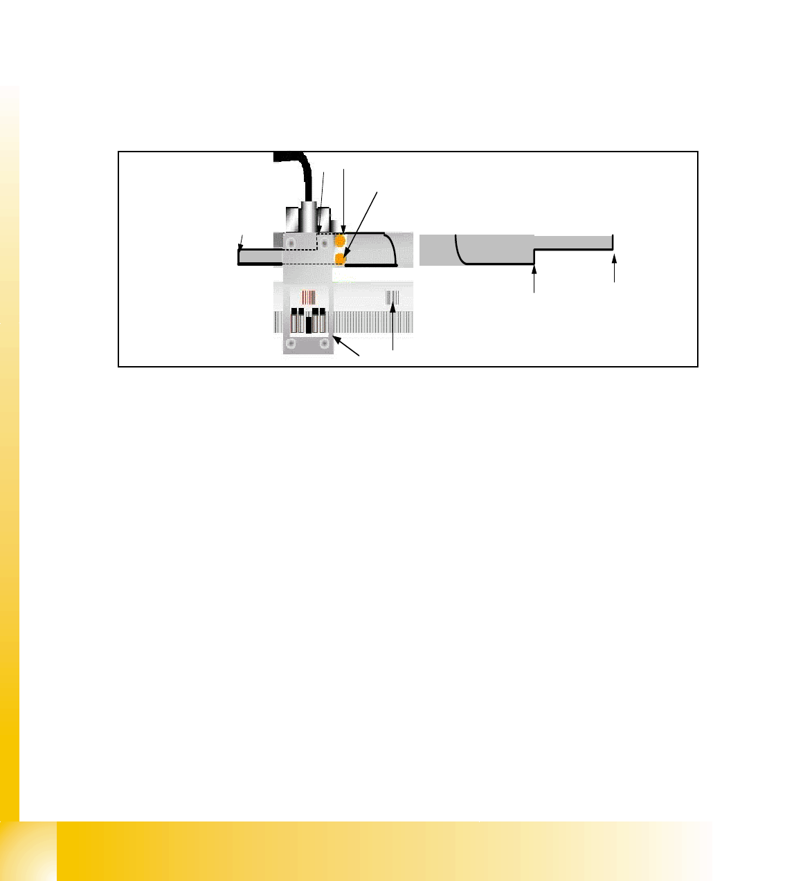
3.2.3 Reference run of X- and Y- axes
Fig. 3.2 - 2 Metal plate for switching position the BERO
1. Metal plate integrated into the machine frame
2. & 2b Switching position for HW-limit switch (Travel range)
3. Switching position for reference BERO / 3b start speed controled mode (near axis endstop)
4. BERO for limit switch (left side)
5. BERO for reference
6. First zero puls on the incremental scale
7. Incremental encoder
– The reference run is done with a defined travel range BERO and the incremental encoder.
– First the gantry axes move to the reference Bero (4).
– If the switching position(3) is detected the direction of movement is reversed and the Zero
pulse signal (6) search starts.
– When the Zero pulse is detected the zero point correction is loaded to the axis controller. Ref-
erence run gantry axes is completed.
– After the whole refernce run of the axes starts the initialization of the Transport system
– All transport motors except Input conveyor and conveyors their light barrier sensor are covered
by a PCB will be activated.
1
2b
3b
6
5
4
7
3
2