AL1_SiplaceX-en.pdf - 第162页
1 - 72 S tudent Guide SIPLACE X 4 Collect &Place-He ad 6/12 Edition 02/2005 72 Notes:
1 - 71
Student Guide SIPLACE X
Edition 02/2005 4 Collect &Place-Head 6/12
71
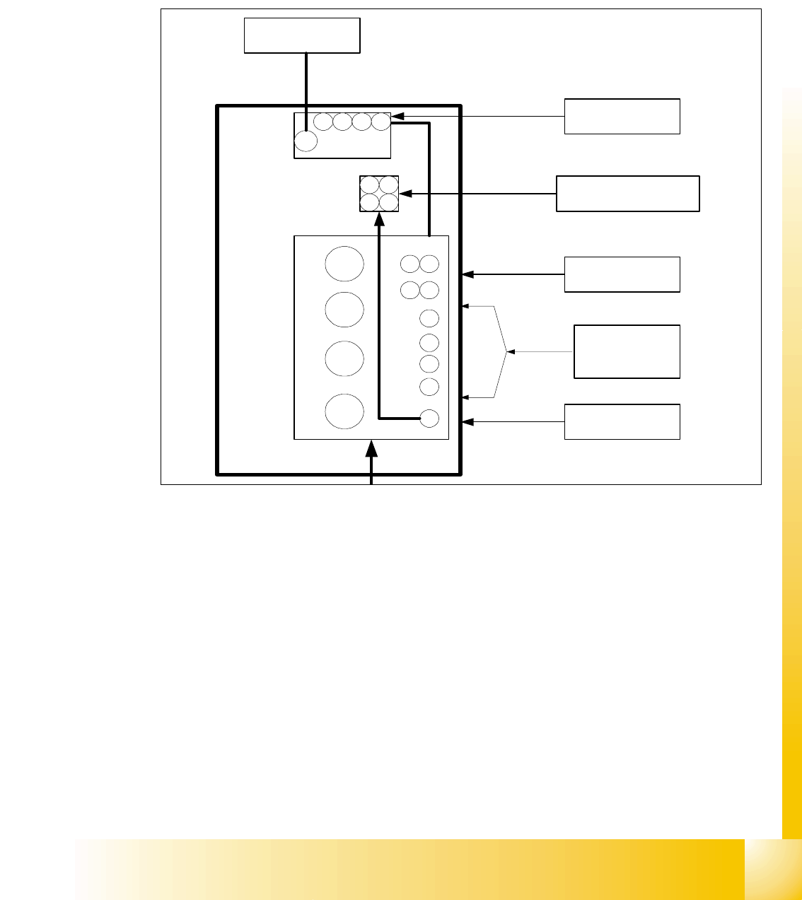
4.5.3 Control nozzle changer on the C&P heads
The nozzle changer are controlled via CAN Bus. Depending on the location at the machine the
SLIO at Main- or Sub-Distributor is used. At HF-machine version ’A’ and SIPLACE X the nozzle
changer is controlled via the "One Wire Bus". Solenoid valves activate the pneumatic rotary drives
to open or close the nozzle changer.
Fig. 4.5 - 4 Pressure air supply for the nozzle changer (pneumatic unit)
3
4
2
1
Gantry 1 - 4
4
3
2
1
Bulkcase
Feeder
COT 1-4
2,5 bar
adjustable
Nozzle
changer
1 2
34
Nozzle changer
Gantry 1 - 4
2,5 bar
adjustable
Docking unit
1 - 4
5 bar
adjustable
Conveyor
5 bar
adjustable
5 bar
adjustable
1 2 3 4
Tape cutter
1 - 4
4 3
21


Student Guide SIPLACE X
Edition 02/2005 Contents
1
Chapter
Table of Contents
5 Collect&Place-Head 20 . . . . . . . . . . . . . . . . . . . . . . . . . . . . . . . . . . . . . . . . . . . . . . . 3
5.1 Overview. . . . . . . . . . . . . . . . . . . . . . . . . . . . . . . . . . . . . . . . . . . . . . . . . . . . . . . . . . . . . . . . . . . . . . . 3
5.1.1 Technical Data C&P 20 Head. . . . . . . . . . . . . . . . . . . . . . . . . . . . . . . . . . . . . . . . . . . 4
5.1.2 Function principle C&P 20 Head . . . . . . . . . . . . . . . . . . . . . . . . . . . . . . . . . . . . . . . . . 5
5.1.3 Parts overview with describtion . . . . . . . . . . . . . . . . . . . . . . . . . . . . . . . . . . . . . . . . . . 6
5.1.3.1 Vacuum generator . . . . . . . . . . . . . . . . . . . . . . . . . . . . . . . . . . . . . . . . . . . . . . . . 7
5.1.3.2 Z-Drive . . . . . . . . . . . . . . . . . . . . . . . . . . . . . . . . . . . . . . . . . . . . . . . . . . . . . . . . . 8
5.1.3.3 Retract unit. . . . . . . . . . . . . . . . . . . . . . . . . . . . . . . . . . . . . . . . . . . . . . . . . . . . . . 9
5.1.3.4 Component Sensor . . . . . . . . . . . . . . . . . . . . . . . . . . . . . . . . . . . . . . . . . . . . . . . 9
5.1.3.5 Star. . . . . . . . . . . . . . . . . . . . . . . . . . . . . . . . . . . . . . . . . . . . . . . . . . . . . . . . . . . 11
5.1.3.6 DP-Drive. . . . . . . . . . . . . . . . . . . . . . . . . . . . . . . . . . . . . . . . . . . . . . . . . . . . . . . 12
5.1.3.7 Star Drive . . . . . . . . . . . . . . . . . . . . . . . . . . . . . . . . . . . . . . . . . . . . . . . . . . . . . . 13
5.1.3.8 Component camera . . . . . . . . . . . . . . . . . . . . . . . . . . . . . . . . . . . . . . . . . . . . . . 14
5.1.3.9 Nozzle Changer . . . . . . . . . . . . . . . . . . . . . . . . . . . . . . . . . . . . . . . . . . . . . . . . . 14
5.1.4 Pressure air supply DLM 2 C&P head. . . . . . . . . . . . . . . . . . . . . . . . . . . . . . . . . . . . 15
5.1.4.1 Holding circuit. . . . . . . . . . . . . . . . . . . . . . . . . . . . . . . . . . . . . . . . . . . . . . . . . . . 15
5.1.4.2 Overview Air kiss supply. . . . . . . . . . . . . . . . . . . . . . . . . . . . . . . . . . . . . . . . . . . 16
5.1.4.3 Overview Vacumm supply . . . . . . . . . . . . . . . . . . . . . . . . . . . . . . . . . . . . . . . . . 17
5.2 Reference Run . . . . . . . . . . . . . . . . . . . . . . . . . . . . . . . . . . . . . . . . . . . . . . . . . . . . . . . . . . . . . . . . . 19
5.2.1 Reference Run for C&P20 Head . . . . . . . . . . . . . . . . . . . . . . . . . . . . . . . . . . . . . . . . 20
5.2.2 Preparing the Z-axis Reference Run. . . . . . . . . . . . . . . . . . . . . . . . . . . . . . . . . . . . . 21
5.2.3 Star Axis Reference Run. . . . . . . . . . . . . . . . . . . . . . . . . . . . . . . . . . . . . . . . . . . . . . 21
5.2.4 Z-Axis Reference Run. . . . . . . . . . . . . . . . . . . . . . . . . . . . . . . . . . . . . . . . . . . . . . . . 22
5.2.5 DP Axis Reference Run. . . . . . . . . . . . . . . . . . . . . . . . . . . . . . . . . . . . . . . . . . . . . . . 23
5.2.6 Vacuum Check Procedure. . . . . . . . . . . . . . . . . . . . . . . . . . . . . . . . . . . . . . . . . . . . . 24
5.2.7 Determining the Vacuum and Threshold Values. . . . . . . . . . . . . . . . . . . . . . . . . . . . 25
5.2.8 Measuring Z- axis position for Component Recognition by the Component Sensor. 26
5.2.9 Height reference run . . . . . . . . . . . . . . . . . . . . . . . . . . . . . . . . . . . . . . . . . . . . . . . . . 27
5.2.10 Sequence of height reference run. . . . . . . . . . . . . . . . . . . . . . . . . . . . . . . . . . . . . . 28
5.3 Pickup and Placement Cycle for Collect & Place Head 20. . . . . . . . . . . . . . . . . . . . . . . . . . . . . . 29
5.3.1 Working Positions at the Placement Head . . . . . . . . . . . . . . . . . . . . . . . . . . . . . . . . 29
5.3.2 20 Nozzle Collect & Place Head in Home Position 0°. . . . . . . . . . . . . . . . . . . . . . . . 30
5.3.3 PCB position recognition and temperature compensation . . . . . . . . . . . . . . . . . . . . 30
5.3.4 PCB Position Recognition - Centering of the PCB Fiducials. . . . . . . . . . . . . . . . . . . 31
5.3.5 Turning Nozzles 1 to 20 to the Pickup Angle (0° or 90°). . . . . . . . . . . . . . . . . . . . . . 32
5.3.6 Check Nozzle Length for Component Recognition . . . . . . . . . . . . . . . . . . . . . . . . . . 32
5.3.7 Picking Up the First Component . . . . . . . . . . . . . . . . . . . . . . . . . . . . . . . . . . . . . . . . 33
5.3.8 Picking Up the 10th Component . . . . . . . . . . . . . . . . . . . . . . . . . . . . . . . . . . . . . . . . 33