AL1_SiplaceX-en.pdf - 第273页
1 - 19 S tudent Guide SIPLACE X Ausgabe 02/2005 7 Sit est 19 7.2.7 Calibrate the conveyor edges – Choose "conveyor edges" fThis function will be direct ly done, there are no furt her adjustment s necessary . De…

1 - 18
Student Guide SIPLACE X
7 Sitest Ausgabe 02/2005
18
7.2.6.2 Twin head
Fig. 7.2 - 7 Sequence Twin head calibration
Ablauf der Kalibrierung desTwin Heads
Maschinennullpunkt
Kalibrierteilposition
LP-Kamera
y
Kamera-Koeffizient (Abbildungsmaßstab in nm/pixel)
y
Kalibrierung des LP-Kamera-Mittelpunktes
y
Kalibrierung der Verdrehung der LP-Kamera zum
Maschinen-Koordinatensystem
Verfahrweg X-/Y-Achse
y
Kalibrierung der min/max Verfahrwege der Portale
Twin head Höhe
y
Kalibrierung der Höhe von Segment 1 und Segment 2
(Die Referenz ist die Oberkante des LP-Transports)
Twin Head Pipettenwechsler
y
Kalibrierung der Abholpositionen für alle Magazine
y
Kalibrierung der Abholhöhe
y
Kalibrierung der Abwurfposition
Twin Head IC-Kamera
y
Fokusebene
y
Kamera-Koeffizient (Einheit -nm/pixel), Winkel
y
IC Kamera Position
Twin Head
y
Offset Segment 1 (LP-Kamera zu Segment 1)
y
Offset Segment 2 (LP-Kamera zu Segment 2)
1 - 19
Student Guide SIPLACE X
Ausgabe 02/2005 7 Sitest
19
7.2.7 Calibrate the conveyor edges
– Choose "conveyor edges"
fThis function will be directly done, there are no further adjustments necessary.
Description for calibrating the conveyor edges see chapter 7.2.14.1
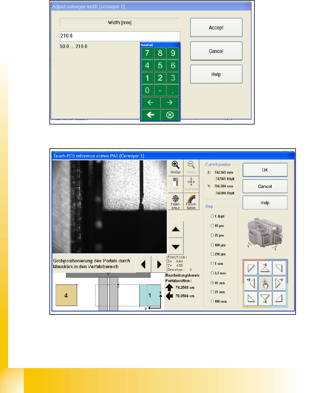
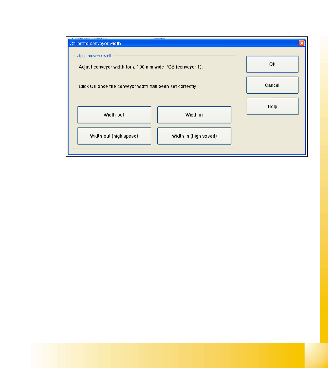
7.2.8 Calibrate the conveyor widths
– Choose "conveyor width..."
Fig. 7.2 - 8 Sub menu calibrate the conveyor width
Description for calibrating the conveyor width see chapter 7.2.14.2