AL1_SiplaceX-en.pdf - 第192页
1 - 30 S tudent Guide SIPLACE X 5 Collect&Place-Head 20 Edition 02/2005 30 5.3.2 20 Nozzle Collect & Place Head in Home Position 0 ° Fig. 5.3 - 2 20 nozzle collect & place head in home position 0° 5.3.3 PCB p…
1 - 29
Student Guide SIPLACE X
Edition 02/2005 5 Collect&Place-Head 20
29
5.3 Pickup and Placement Cycle for Collect & Place
Head 20
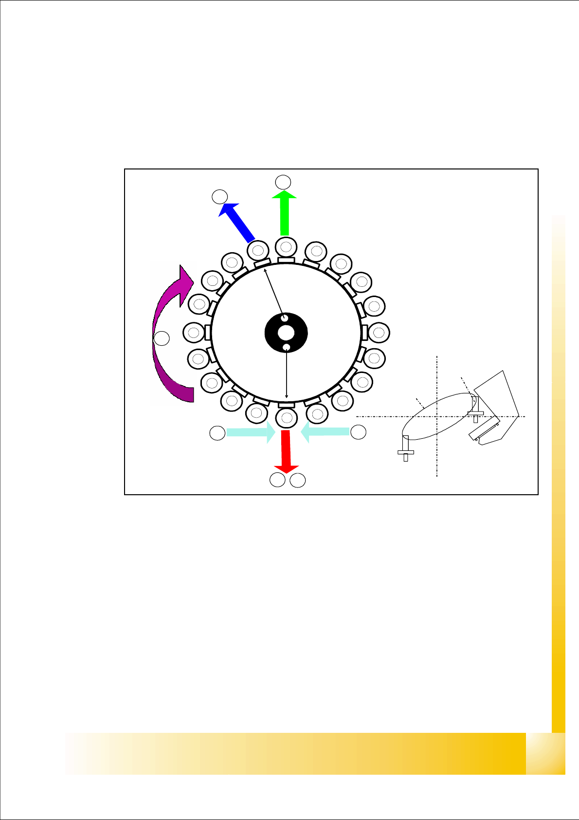
5.3.1 Working Positions at the Placement Head
Fig. 5.3 - 1 Working positions at the placement head
Key
(1) Optical centering (component camera)
(2) Vacuum measurement holding circuit
(3) Vacuum measurement placement circuit
(4) Pickup/placement station and reject position
(5) Position of component sensor
(6) Working direction
1
1
2
3
4
5
5
6
1
2
3
4
5
6
7
8
9
10
12
11
13
14
15
16
17
18
19
20
Segment 1
Segment 11
Co.-
Camera
S
t
a
r
p
o
s
i
t
i
o
n
,
6
16
1 - 30
Student Guide SIPLACE X
5 Collect&Place-Head 20 Edition 02/2005
30
5.3.2 20 Nozzle Collect & Place Head in Home Position 0
°
Fig. 5.3 - 2 20 nozzle collect & place head in home position 0°
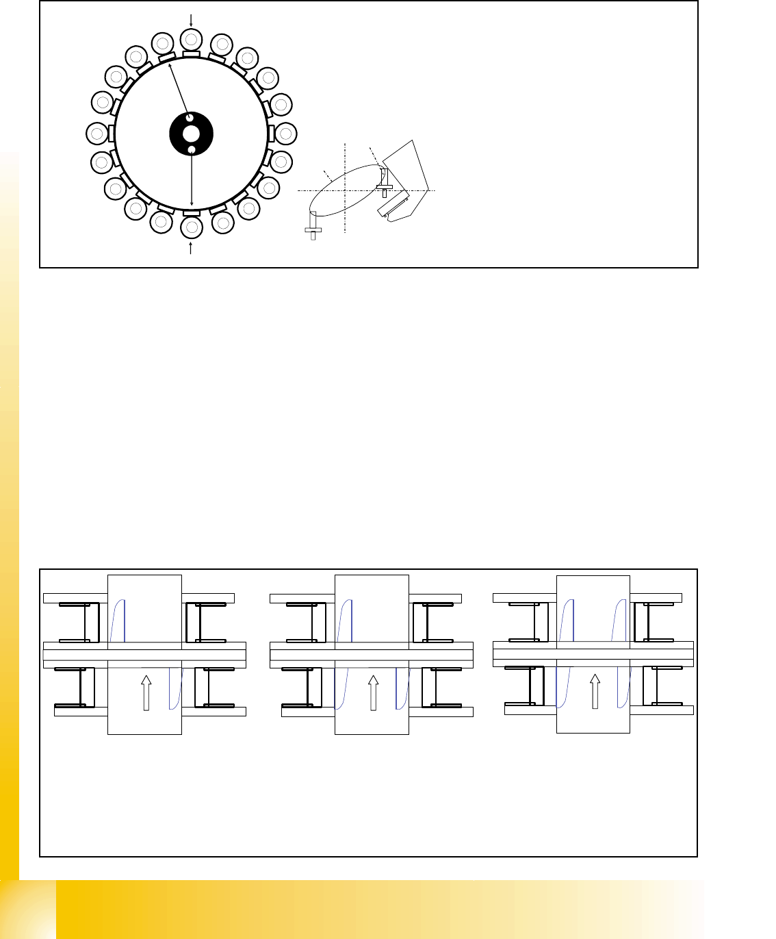
5.3.3 PCB position recognition and temperature compensation
The PCB recognition is necessary to determined the correct position of the PCB in the machine
(Transport --> Placement area).
It should be two fiducials on each PCB minimum. With this two fiducial we are able to determined
the X/Y position and the angle of the PCB in the transport. The fiducials shouldn‘t be in one line
on the PCB.
Up to 3 fiducials can program for the PCB recognition. With the third fiducial, we determined ad-
ditional to the position of the PCB the geometric data of the PCB layout, that means is the PCB
stretch.
The Siplace X machine increase the accuracy, so that we make additional to the PCB recognition
a temperature compensation with the second gantry in the placement area.
the
Star
axis
is
turned
to
home
position
Placement position
CO-
Camera position
1
2
3
4
5
6
7
8
9
10
12
11
13
14
15
16
17
18
19
20
Segment 1
Segment 11
S
t
a
r
p
o
s
i
t
i
o
n
CO- Camera
Star position
Digit: 10
Angle: 0°
1° is equivalent to 1000 digits
The Z-axis retract unit prevents seg-
ment 1 from falling.
TSP
30
1
Gantry 1
Gantry 3
Gantry 4
Siplace X 3
TSP
30
1
Gantry 1
Gantry 3
Gantry 4
Transport
direction
Siplace X 4
Gantry 2
TSP
30
1
Gantry 1
Gantry 2
Siplace X 2
Transport
direction
Transport
direction
Gantry 1 and 2 PCB recog-
nition with max. 3 fiducials
Gantry 4 PCB recognition with
max. 3 fiducials Gantry 3 with
2 fiducials
Gantry 1 temperature compensa-
tion with 2 fiducials.
Gantryl 4 PCB recognition with
max. 3 fiducials Gantry 2 with
2 fiducials
Gantry 1 and 3 temperature com-
pensation with 2 fiducials.
1 - 31
Student Guide SIPLACE X
Edition 02/2005 5 Collect&Place-Head 20
31
Fig. 5.3 - 3 PCB position recognition run to the PCB nominal position
– PCB position recognition is performed before the first component is picked up.
– The gantry axes move the PCB camera to the theoretical fiducial position. The camera takes
the picture of the first fiducial and the vision system calculates the center position.
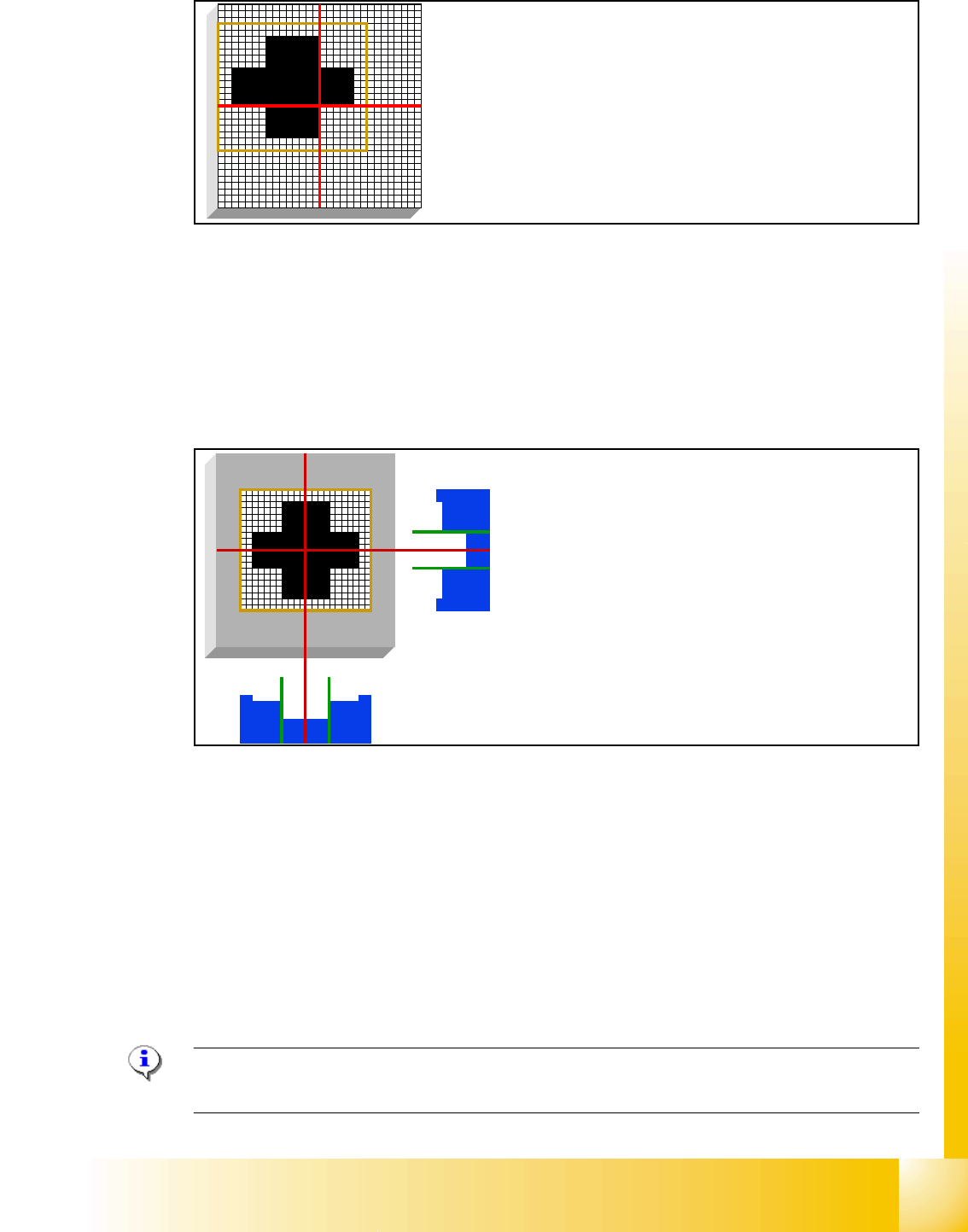
5.3.4 PCB Position Recognition - Centering of the PCB Fiducials
Fig. 5.3 - 4 PCB position recognition - centering of the PCB fiducials
– The camera takes the picture of the second fiducial and the vision system calculates the center
position of this picture.
– With both fiducial positions is the board position and board angle calculated.
– All board fiducials are optically centered with this procedure.
– This data is sent to the machine controller
– The correction values are calculated for the X, Y and the angular position of the PCB and the
board internal dilation.
– Now the gantry axes move the placement head to the first pick up position.
PLEASE NOTE: If synthetic fiducials are used, this does not change the described sequence,
although inkspot recognition will now be performed after fiducial recognition. 5
The fiducial is expected at this nominal position. The PCB cam-
era is moved from waiting position to this fiducial position.
The centered fiducial now defines the actual posi-
tion of the board.