AL1_SiplaceX-en.pdf - 第71页
S tudent Guide SIPLACE X Edition 02/2005 Contents 1 Chapter T able of Content s 3 Gantry . . . . . . . . . . . . . . . . . . . . . . . . . . . . . . . . . . . . . . . . . . . . . . . . . . . . . . . . . . . . . 3 3.1 Ove…
1 - 46
Student Guide SIPLACE X
2 Overview Edition 02/2005
46
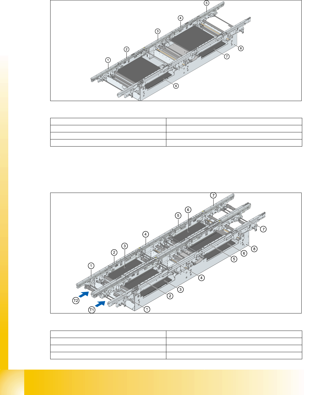
2.2.13.2 Construction of Single Conveyor
The single conveyor consists of the input conveyor, two placements areas, intermediate conveyor
and output conveyor. Each conveyor has automatic width adjustment and a lifting table for clamp-
ing the PCB.
Fig. 2.2 - 29 Construction of PCB conveyor
2.2.13.3 Construction of Dual Conveyor
Dual conveyors have two transportation tracks (1 and 2). In the standard conveyor, the right-hand
side of each track is the fixed side. The fixed conveyor side can be changed to the left, where re-
quired.
Fig. 2.2 - 30 Construction of dual conveyort
(1)Input conveyor (2)Conveyor for placement area 1
(3)Intermediate conveyor (4)Conveyor for placement area 2
(5)Output conveyor (6)Lifting table 1
(7)Lifting table 2 (8)Conveyor vat
(1)Input conveyor (2)Conveyor for placement area 1
(3)Lifting table 1 (4)Intermediate conveyor
(5)Conveyor for placement area 2 (6)Lifting table 2
(7)Output conveyor (8)Conveyor vat

Student Guide SIPLACE X
Edition 02/2005 Contents
1
Chapter
Table of Contents
3 Gantry. . . . . . . . . . . . . . . . . . . . . . . . . . . . . . . . . . . . . . . . . . . . . . . . . . . . . . . . . . . . . 3
3.1 Overview Gantry . . . . . . . . . . . . . . . . . . . . . . . . . . . . . . . . . . . . . . . . . . . . . . . . . . . . . . . . . . . . . . . . 3
3.1.1 Mechanical structur of the X- and Y- axes. . . . . . . . . . . . . . . . . . . . . . . . . . . . . . . . . . 5
3.1.2 Pneumatic connectors on the gantry. . . . . . . . . . . . . . . . . . . . . . . . . . . . . . . . . . . . . . 6
3.2 Reference run Gantry . . . . . . . . . . . . . . . . . . . . . . . . . . . . . . . . . . . . . . . . . . . . . . . . . . . . . . . . . . . . 7
3.2.1 Sequence reference run at X- and Y-axis . . . . . . . . . . . . . . . . . . . . . . . . . . . . . . . . . . 7
3.2.2 X and Y commutation position search. . . . . . . . . . . . . . . . . . . . . . . . . . . . . . . . . . . . . 8
3.2.3 Reference run of X- and Y- axes. . . . . . . . . . . . . . . . . . . . . . . . . . . . . . . . . . . . . . . . . 8
3.3 Adjustments . . . . . . . . . . . . . . . . . . . . . . . . . . . . . . . . . . . . . . . . . . . . . . . . . . . . . . . . . . . . . . . . . . . . 9
3.3.1 Travel range and velocity monitoring X- and Y- Axes on the X2. . . . . . . . . . . . . . . . . 9
3.3.2 Travel range and velocity monitoring X- and Y- Axes on the X3. . . . . . . . . . . . . . . . 10
3.3.2.1 Adjustments BERO‘s . . . . . . . . . . . . . . . . . . . . . . . . . . . . . . . . . . . . . . . . . . . . . 11
3.3.2.2 Description of the BERO‘s on the Y-Axis . . . . . . . . . . . . . . . . . . . . . . . . . . . . . . 11
3.3.3 Description of the PCB boards on the Gantry . . . . . . . . . . . . . . . . . . . . . . . . . . . . . . 12
3.3.3.1 Head interface C500 . . . . . . . . . . . . . . . . . . . . . . . . . . . . . . . . . . . . . . . . . . . . . 12
3.3.3.2 Vision board (digital). . . . . . . . . . . . . . . . . . . . . . . . . . . . . . . . . . . . . . . . . . . . . . 14
3.3.3.3 CAN Processorboard 16 Bit . . . . . . . . . . . . . . . . . . . . . . . . . . . . . . . . . . . . . . . . 15
3.3.3.4 Check the DIP Switches. . . . . . . . . . . . . . . . . . . . . . . . . . . . . . . . . . . . . . . . . . . 16
3.3.4 Anti crash board . . . . . . . . . . . . . . . . . . . . . . . . . . . . . . . . . . . . . . . . . . . . . . . . . . . . 18
3.3.5 Mechanical adjustment the incremental encoder . . . . . . . . . . . . . . . . . . . . . . . . . . . 19

1 - 2
Student Guide SIPLACE X
Contents Edition 02/2005
2