AL1_SiplaceX-en.pdf - 第276页
1 - 22 S tudent Guide SIPLACE X 7 Sitest Ausgabe 02/2005 22 7.2.1 1 LP- Mapping – Choose "LP- Mapping..." Fig. 7.2 - 12 Menu LP- Mapping Description for LP- Mappin g see chapter 7.2.15 7.2.12 Head- Mapping – Ch…
1 - 21
Student Guide SIPLACE X
Ausgabe 02/2005 7 Sitest
21
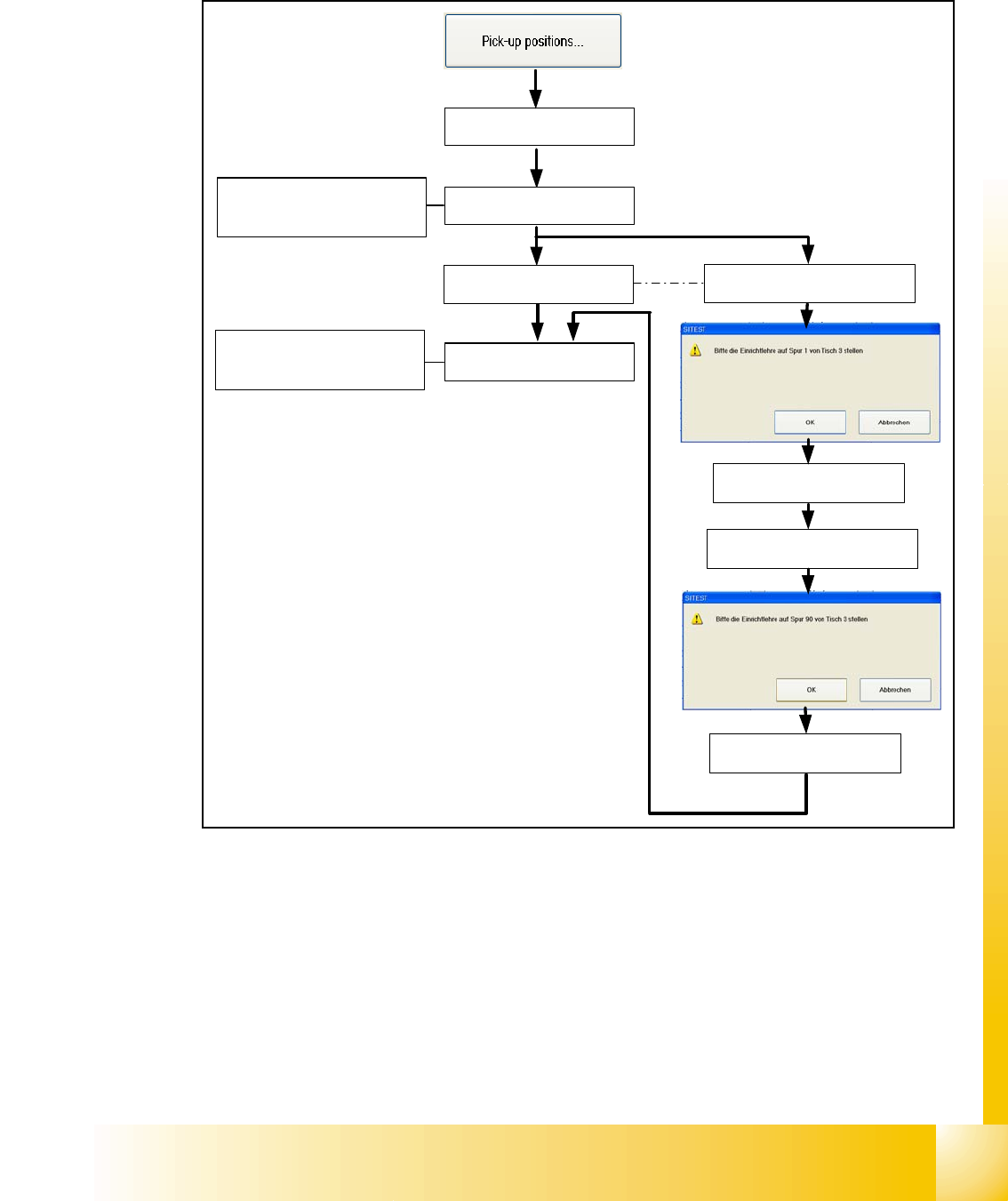
7.2.10 Calibrate the Pick up position
– Choose "pick-up positions..."
Fig. 7.2 - 11 Calibrate the Pick up position
There are a few opportunities to put on different table types on the machine. The pick up position
of the X- tables are automatically calibrated (Calibrate fiducials for pick up position are mounted
on the table). The S- tables must be manually calibrated with the adjusment gauge like it was at
the older machine types. If there is a MTC2 placed at location 2 or 4 this location will be automat-
ically skipped during calibrating the pick up position.
Description for calibrating the pick up positions see chapter 7.2.14.4 and 7.2.14.5
X- table 1 will be
automatically calibrated
If a MTC2 is placed at this
location, this step will be
automatically skipped
If a S- table 3 is placed, put the
adjustment gauge on track 1
Calibrate Track 1
Calibrate Track 90
If a S- table is placed, put the
adjustment gauge on track 90
If a MTC2 is placed at this
location, this step will be
automatically skipped
X- table 2 will be
automatically calibrated
X- table 3 will be
automatically calibrated
X- table 4 will be
automatically calibrated
1 - 22
Student Guide SIPLACE X
7 Sitest Ausgabe 02/2005
22
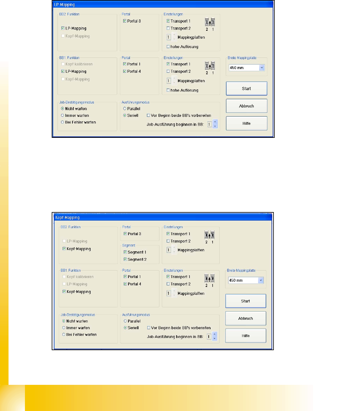
7.2.11 LP- Mapping
– Choose "LP- Mapping..."
Fig. 7.2 - 12 Menu LP- Mapping
Description for LP- Mapping see chapter 7.2.15
7.2.12 Head- Mapping
– Choose "Head- Mapping..."
Fig. 7.2 - 13 Menu Head- Mapping
Description for Head- Mapping see chapter 7.2.16
1 - 23
Student Guide SIPLACE X
Ausgabe 02/2005 7 Sitest
23
7.2.13 Basically description of all calibration steps
Machine zero point: 7
– The PCB-camera center is the reference at the gantry. All positions at the incremental encoder
of X/Y-axis refer to this camera center.
– A drilling is optically centered with the PCB-camera on a defined position at the calibration tool
support.
– Then the Zero point correction of the gantry axes are changed that if the PCB camera is above
this hole and the Positioncounter shows exactly the value of:
MA nullpunkt_x_PG1 631300 / MA nullpunkt_y_PG1 1298000. ( pg means gantry group)
MA nullpunkt_x_PG2 1368700 / MA nullpunkt_y_PG2 702000 ( See Fig. 7.2 - 2)
PCB camera: 7
– The Pixel size of the CCD sensors of the camera is determined in µm. Measured and calcu-
lated with Ax/Bx/Ay/By calibration values. Saved in KAM_DAT.MA as:XU_Pixel / YU_Pixel
(in 11600 nm Standard-PCB camera SST 5), (in 9900 nm Multicolorillum. PCB camera SST 18)
– The camera center is determined.
– This camera center is now the reference for all Position and Offsets of the gantry!!
– The Mounting angle of the CCD-chip in the camera to the Ma-coordinate system. Saved as
‘Kamera_winkel’ at the Data bloc of the PCB camera in KAMDAT.MA.
Calibration tool position:(optional) 7
– Calibrate the X and Y pick up position of the calibration tool.
Travel range:(optional) 7
– For travel range calibration move the respective axis: -to the Zero-pulse
– Then to the Hardware-limit switch
– Measure the position value at the position counter
– Calculate the position for SW-limit switch (Y +/- 1.5 mm , X +/- 0,5 mm)
65mm
Turning for reference run
speed monitoring
Speed monitoring
HW travel range
HW travel range
Y-Axis
45mm
Turning for refere nc e run
Speed monitoring
HW tra ve l ra nge
HW tra ve l ra nge
Speed monitoring
X-Axis