AL1_SiplaceX-en.pdf - 第72页
1 - 2 S tudent Guide SIPLACE X Contents Edition 02/2005 2

Student Guide SIPLACE X
Edition 02/2005 Contents
1
Chapter
Table of Contents
3 Gantry. . . . . . . . . . . . . . . . . . . . . . . . . . . . . . . . . . . . . . . . . . . . . . . . . . . . . . . . . . . . . 3
3.1 Overview Gantry . . . . . . . . . . . . . . . . . . . . . . . . . . . . . . . . . . . . . . . . . . . . . . . . . . . . . . . . . . . . . . . . 3
3.1.1 Mechanical structur of the X- and Y- axes. . . . . . . . . . . . . . . . . . . . . . . . . . . . . . . . . . 5
3.1.2 Pneumatic connectors on the gantry. . . . . . . . . . . . . . . . . . . . . . . . . . . . . . . . . . . . . . 6
3.2 Reference run Gantry . . . . . . . . . . . . . . . . . . . . . . . . . . . . . . . . . . . . . . . . . . . . . . . . . . . . . . . . . . . . 7
3.2.1 Sequence reference run at X- and Y-axis . . . . . . . . . . . . . . . . . . . . . . . . . . . . . . . . . . 7
3.2.2 X and Y commutation position search. . . . . . . . . . . . . . . . . . . . . . . . . . . . . . . . . . . . . 8
3.2.3 Reference run of X- and Y- axes. . . . . . . . . . . . . . . . . . . . . . . . . . . . . . . . . . . . . . . . . 8
3.3 Adjustments . . . . . . . . . . . . . . . . . . . . . . . . . . . . . . . . . . . . . . . . . . . . . . . . . . . . . . . . . . . . . . . . . . . . 9
3.3.1 Travel range and velocity monitoring X- and Y- Axes on the X2. . . . . . . . . . . . . . . . . 9
3.3.2 Travel range and velocity monitoring X- and Y- Axes on the X3. . . . . . . . . . . . . . . . 10
3.3.2.1 Adjustments BERO‘s . . . . . . . . . . . . . . . . . . . . . . . . . . . . . . . . . . . . . . . . . . . . . 11
3.3.2.2 Description of the BERO‘s on the Y-Axis . . . . . . . . . . . . . . . . . . . . . . . . . . . . . . 11
3.3.3 Description of the PCB boards on the Gantry . . . . . . . . . . . . . . . . . . . . . . . . . . . . . . 12
3.3.3.1 Head interface C500 . . . . . . . . . . . . . . . . . . . . . . . . . . . . . . . . . . . . . . . . . . . . . 12
3.3.3.2 Vision board (digital). . . . . . . . . . . . . . . . . . . . . . . . . . . . . . . . . . . . . . . . . . . . . . 14
3.3.3.3 CAN Processorboard 16 Bit . . . . . . . . . . . . . . . . . . . . . . . . . . . . . . . . . . . . . . . . 15
3.3.3.4 Check the DIP Switches. . . . . . . . . . . . . . . . . . . . . . . . . . . . . . . . . . . . . . . . . . . 16
3.3.4 Anti crash board . . . . . . . . . . . . . . . . . . . . . . . . . . . . . . . . . . . . . . . . . . . . . . . . . . . . 18
3.3.5 Mechanical adjustment the incremental encoder . . . . . . . . . . . . . . . . . . . . . . . . . . . 19

1 - 2
Student Guide SIPLACE X
Contents Edition 02/2005
2
1 - 3
Student Guide SIPLACE X
Edition 02/2005 3 Gantry
3
3Gantry
3.1 Overview Gantry
The gantries of the Siplace X machine consist of one X- and one Y - axis. Both axes are driven by
a linear motor which is equipped with an integrated temperature sensor. The Y-axis moves from
the right to the left side in positive counting direction if you look in transportation direction, the X-
axis moves from the the input conveyor to the output conveyer in positive counting direction. The
placement heads are mounted on the head plates of the respective X axis.
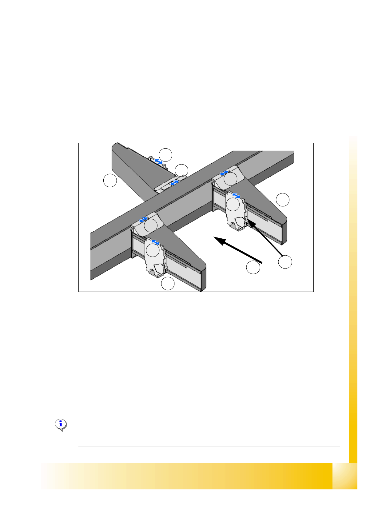
Fig. 3.1 - 1 Position of the gantries e.g. X3
Legend:
Note:
On the Siplace X and HF-Machines it is possible, that we use two different kind of gantries.
So we recognize the gantry type with an Eprom and load automatically the right machine
data (CFK 02 or CFK 04).
G1Gantry 1 in PA1 G3Gantry 3 in PA2
X1X-Axis, Gantry 1 X3X-Axis, Gantry 3
Y1Y-Axis, Gantry 1 Y3Y-Axis, Gantry 3
G4Gantry 4 in PA 1
X4X-Axis, Gantry 4 (T)Transportation direction
Y4Y-Axis, Gantry 4 (TS)Temperature sensor on each head mounting plate
G4
G1
G3
Y4
Y3
Y1
X4
X3
X1
T
TS