AL1_SiplaceX-en.pdf - 第40页
1 - 16 S tudent Guide SIPLACE X 2 Overview Edition 02/2005 16 2.2.5 Axis Unit The axis unit contains th e servo boards, axis ca rds, power supplies (+/-15V ,+5V), ballast circuit and anti-crash board. T he flexible axis …
1 - 15
Student Guide SIPLACE X
Edition 02/2005 2 Overview
15
2.2.4 Computer Unit
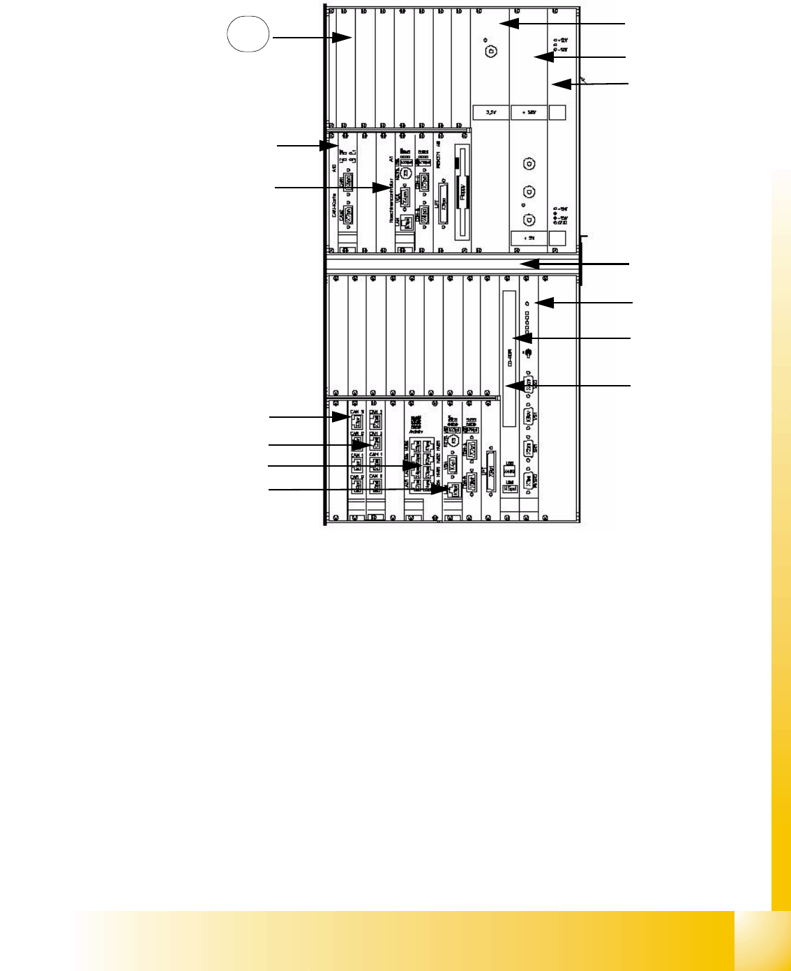
Fig. 2.2 - 5 Computer unit
Key
(1) Power supply for DC/DC converter 3.3V
(CPUs)
(2) Power supply for DC/DC converter 52V /
+5V 60A
(3) Power supply for DC/DC converter +/-12V
(+/-15V not used)
(4) Fan unit (blows downwards)
(5) Video multiplexer (6) CD-ROM drive with USB port
(7) COM unit 1Mbit/s, connection at top for
BB 1 / connection at bottom for BB 2
(8) CPU unit machine control (MC)
(9) Hotlink card for cameras (BB1) (10) Hotlink card for cameras (BB2)
(11) Dual LAN unit (12) CPU unit station computer (SC)
(13) Space for CPU unit Vision computer
(for BB2, option)
1
2
3
4
5
7
8
9
10
11
12
13
6
3.6V back-up bat-
tery on the rear of
the computer unit
1 - 16
Student Guide SIPLACE X
2 Overview Edition 02/2005
16
2.2.5 Axis Unit
The axis unit contains the servo boards, axis cards, power supplies (+/-15V,+5V), ballast circuit
and anti-crash board. The flexible axis (servo) unit is equipped with servo boards/axis cards ac-
cording the machine/head configuration.
Overview of axis unit
X2 machine axis unit in BB2 for gantries 1 and 3
X3 machine axis unit in BB1 for gantries 1 and 4, axis unit in BB2 for gantry 3
X4 machine axis unit in BB1 for gantries 1 and 4, axis unit in BB2 for gantries 2 and 3
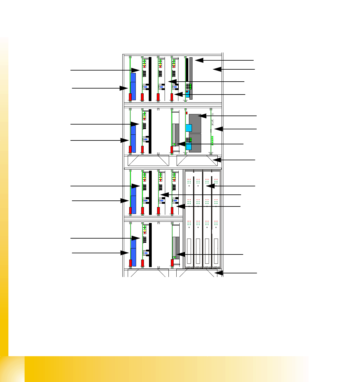
2.2.5.1 Example of Axis Unit for X4/ X3 with Two C&P20 Heads in Placement Area 1
(1) Power supply +/-15V, +5V (2) Ballast circuit board, only in axis unit BB2
(3) Power supply +/-15V (4) Anti-crash board
(5) Fan unit (blows downwards)
(6) Axis cards A363
(7) Servo amplifier for X-axis (8) Servo amplifier for Y-axes
(9) Brake board for each X-axis and Y-axis
(10)
TBS 250/10X
TBS 250 /20Y
DBM/3P-06
SDS 120/2.5S1-03
5 V / 15A 15V/1,7A 15V/ 1,7A
DC/ DC Wandler Dp-Antriebe
DBM/3P-06
TBS 250/10X
TBS 250 /20Y
DBM/3P-06
SDS 120/2.5S1-03
SDS 60 2.5Z1-02
DBM/3P-06
SDS 60/2.5Z1-02
15 V / 5A 15 V / 5A
Anti crash board
DC/ DC Wandler Dp-Antriebe
X
Y
Stern
Stern
X
Y
Frei
Frei
Z
Z
Frei
Frei
Portal 1
Portal 4
1
2
3
4
5
6
7
9
8
9
7
9
8
9
Placement area 1
Gantry 1
Placement area 1
Gantry 4
5
Servo star axis
Servo Z-axis
DC/DC converter
DP drives
DC/DC converter
DP drives
Servo Z-axis
Servo star axis
1 - 17
Student Guide SIPLACE X
Edition 02/2005 2 Overview
17
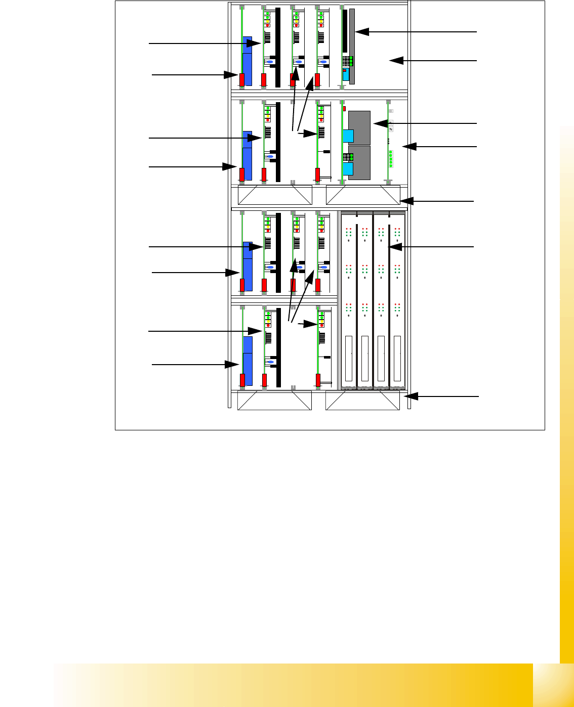
2.2.5.2 Example of Axis Unit for X4/ X3 with Two DLM Heads in Placement Area 1
Fig. 2.2 - 6 Axis unit PA1 with DLM Heads
Key
(1) DC/DC converter 5V/15A for axis unit (2)
Ballast circuit board, only in axis unit BB2
(3) DC/DC converter +/-15V for gantries and
head interface, 5V CAN BUS
(4) Anti crash board
(5) Fan unit (blow downwards) (6) Axis boards A363
(7) Servo boards X-axis, placement area 1 for gan-
tries 1/4
(8) Servo boards Y-axis, placement area 1 for gan-
tries 1/4
(9) Brake board for each X and Y axis
(10) Servo boards for star-/Z-/DP-axes
TBS 250/10X
TBS 250 /20Y
DBM/3P-06
SDS 120/2.5S1-03
5 V / 15A 15V/1,7A 15V/ 1,7A
SDS 60/1D1-02
DBM/3P-06
TBS 250/10X
TBS 250 /20Y
DBM/3P-06
SDS 120/2.5S1-03
SDS 60 3Z1-02
SDS 60/1D1-02
DBM/3P-06
SDS 60/3Z1-02
15 V / 5A 15 V / 5A
Anti crash board
Portal 1
Portal 4
X Z
X
Z
Y
dp
X
Stern Frei
dp
Stern Frei
1
2
3
4
5
6
7
9
8
9
7
9
8
9
Placement area 1
Gantry 1
Placement area 1
Gantry 4
5
10
10