AL1_SiplaceX-en.pdf - 第165页
1 - 3 S tudent Guide SIPLACE X Edition 02/2005 5 Collect&Place-Head 20 3 5 Collect&Place-Head 20 5.1 Overview The Siplace X machine have, depend ing on your configuration , max. 4 C&P 20 heads on a X4, with a…

1 - 2
Student Guide SIPLACE X
Contents Edition 02/2005
2
5.3.9 Picking Up the 11th Component . . . . . . . . . . . . . . . . . . . . . . . . . . . . . . . . . . . . . . . . 34
5.3.10 Picking Up the 12th Component . . . . . . . . . . . . . . . . . . . . . . . . . . . . . . . . . . . . . . . 34
5.3.11 Picking Up the 13th Component . . . . . . . . . . . . . . . . . . . . . . . . . . . . . . . . . . . . . . . 35
5.3.12 Picking Up the 20th Component . . . . . . . . . . . . . . . . . . . . . . . . . . . . . . . . . . . . . . . 35
5.3.13 Component recognition at the 1st Segment by Component Sensor . . . . . . . . . . . . 36
5.3.14 Placing the 1st Component . . . . . . . . . . . . . . . . . . . . . . . . . . . . . . . . . . . . . . . . . . . 36
5.3.15 Component Sensor Checks Segment 1 . . . . . . . . . . . . . . . . . . . . . . . . . . . . . . . . . 37
5.3.16 Placing the 10th Component . . . . . . . . . . . . . . . . . . . . . . . . . . . . . . . . . . . . . . . . . . 37
5.3.17 Placing the 11th Component . . . . . . . . . . . . . . . . . . . . . . . . . . . . . . . . . . . . . . . . . . 38
5.3.18 Placing the 20th Component . . . . . . . . . . . . . . . . . . . . . . . . . . . . . . . . . . . . . . . . . . 38
5.3.19 Pickup and Placement Cycle for the Next Components.... . . . . . . . . . . . . . . . . . . . 39
5.3.20 Segment with a „Defective Component“ . . . . . . . . . . . . . . . . . . . . . . . . . . . . . . . . . 39
5.3.21 Finishing PCB Placement . . . . . . . . . . . . . . . . . . . . . . . . . . . . . . . . . . . . . . . . . . . . 39
5.3.22 Positioning to Pickup/Placement Angle . . . . . . . . . . . . . . . . . . . . . . . . . . . . . . . . . . 40
5.3.23 Detailed Standard Pickup Sequence: Z-axis Downwards . . . . . . . . . . . . . . . . . . . . 40
5.3.24 Detailed Standard Pickup Sequence: Z-axis Upwards . . . . . . . . . . . . . . . . . . . . . . 41
5.3.25 Standard Placement Mode: Z-Axis Downwards . . . . . . . . . . . . . . . . . . . . . . . . . . . 42
5.3.26 Standard Placement Mode: Z-Axis Upwards. . . . . . . . . . . . . . . . . . . . . . . . . . . . . . 43
5.3.27 Optical nozzle scanning. . . . . . . . . . . . . . . . . . . . . . . . . . . . . . . . . . . . . . . . . . . . . . 44
5.4 Adjustments . . . . . . . . . . . . . . . . . . . . . . . . . . . . . . . . . . . . . . . . . . . . . . . . . . . . . . . . . . . . . . . . . . . 45
5.4.1 Description of the PCB boards on the C&P head . . . . . . . . . . . . . . . . . . . . . . . . . . . 45
5.4.1.1 Head adapter 20 C&P head . . . . . . . . . . . . . . . . . . . . . . . . . . . . . . . . . . . . . . . . 45
5.4.1.2 Arrangement of Intermediate distributor 20 C&P head (003005158-0X) . . . . . . 46
5.4.2 Spare part overview and settings at 20 C&P head . . . . . . . . . . . . . . . . . . . . . . . . . . 50
5.5 Nozzle changer. . . . . . . . . . . . . . . . . . . . . . . . . . . . . . . . . . . . . . . . . . . . . . . . . . . . . . . . . . . . . . . . . 51
5.5.1 Nozzle changer for 20 segment C&P head . . . . . . . . . . . . . . . . . . . . . . . . . . . . . . . . 51
5.5.2 Detail view of nozzle changer 20 segment C&P- head . . . . . . . . . . . . . . . . . . . . . . . 52
5.5.3 Assembly with adjusting tool of nozzle changer 20 segment C&P- head . . . . . . . . . 53
5.5.4 Control unit for nozzle changer of the C&P heads. . . . . . . . . . . . . . . . . . . . . . . . . . . 54
5.5.5 Pneumatic plan for nozzle changer . . . . . . . . . . . . . . . . . . . . . . . . . . . . . . . . . . . . . . 54
1 - 3
Student Guide SIPLACE X
Edition 02/2005 5 Collect&Place-Head 20
3
5 Collect&Place-Head 20
5.1 Overview
The Siplace X machine have, depending on your configuration, max. 4 C&P 20 heads on a X4,
with a X3 max. 2 C&P 20 heads and one C&P 20 head on the X2 machine (see chapter overview).
5
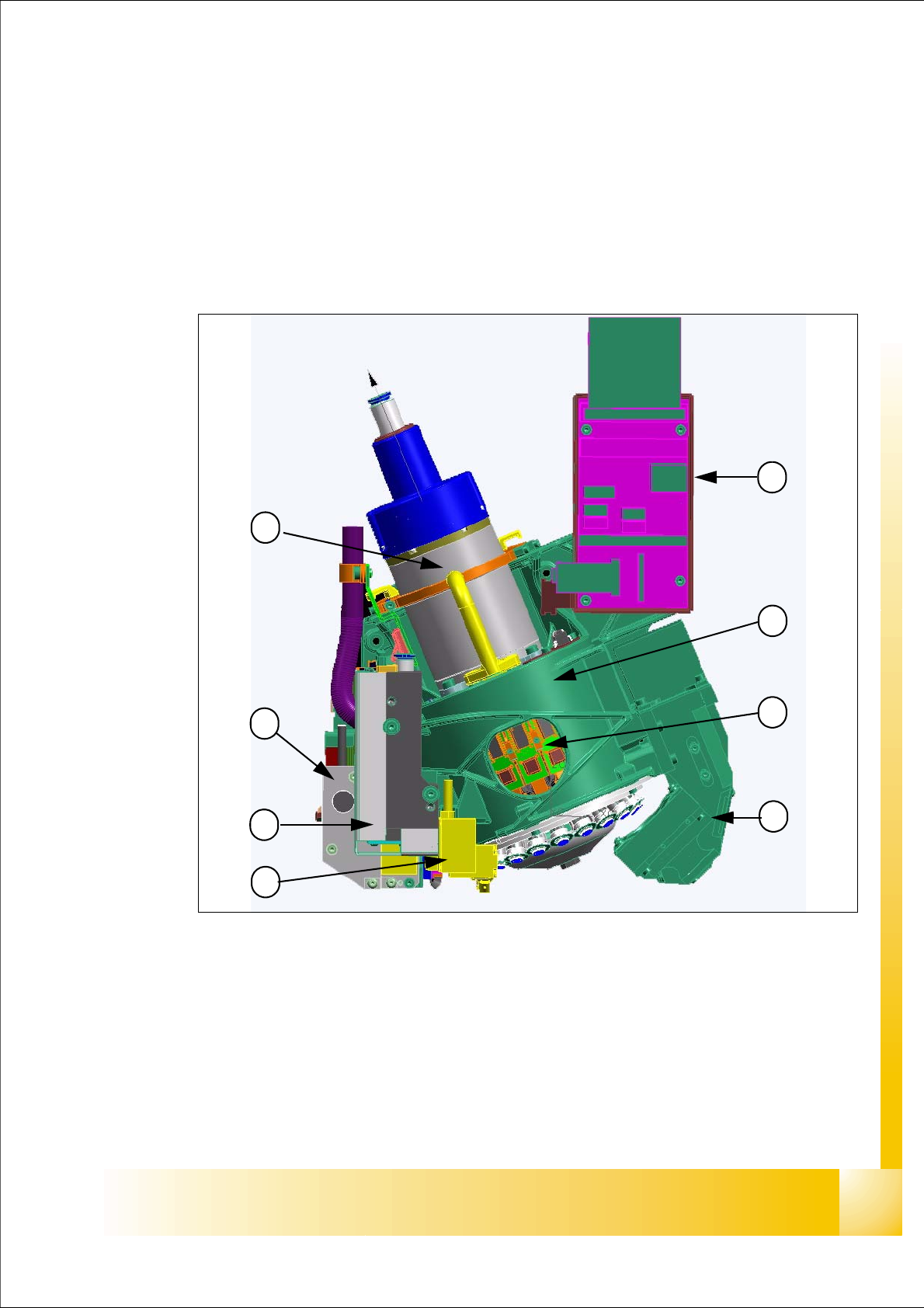
Fig. 5.1 - 1 Collect&Place20 Head- Overview
Legend
(1) Head Housing (2) Star, mounted with 20 DP-Drives
(3) Component camera (4) Intermediate distributor
(5) Component -sensor (6) Vacuum generator (digital)
(7) Z-Axis with incremental encoder (8) Star motor with incremental encoder
1
6
5
4
3
2
7
8
1 - 4
Student Guide SIPLACE X
5 Collect&Place-Head 20 Edition 02/2005
4
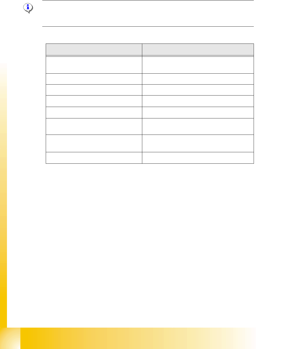
5.1.1 Technical Data C&P 20 Head
PLEASE NOTE: Head modularity
After exchange the head the axes dynamic will be adjust automatically from the axes data base
at the configuration setting.
.
Description C&P20- head
Component size
01005 up to 2220, Melfs, Bare Dies, Flip Chip´s,
SOT, SOD, BE´s up to max. 6x6mm
Component height 4,0 mm
Component weight max. 1g
Placement Accuracy
+/- 50µm at 4 (Sigma)
Angle Accuracy
+/- 0,8° at 4 (Sigma)
Placement force
2,0N +/- 0,5N
3,5N and 4,5N +/- 1N
Nozzle types
1001, 1003, 1004, 1006, 1011, 1032-1037
1235 for calibration tool of the C&P 20 head
Nozzle changer
set up for each 6 magazine with 12 garage,
Table 5.1 - 1 Technical data 20 Segment C&P head