EUKYX-199-4110_G5S2_Instruction_Vol4_E.pdf - 第114页
EUKYX 1-65 199-4100 5.4 Method of Blow air 5.4 Meth od of Blo w a ir • Remove dust and dirt etc. Remo ve s l igh t dust and di r t by bl owi ng air or w ipi ng of f . Clea n the taper ed area of the vac uum nozz le with …
EUKYX
1-64199-4100
5.2 Method of detaching vacuum nozzles
5.2 Method of detaching vacuum nozzles
• Store the nozzles in the nozzle stocker (housing) through window navigations and take out the
nozzle stocker (housing).
(a) Do not take out a nozzle from the head by hand. Otherwise, the nozzle does not
conform to the nozzle data.
(b) Do not blow air to the vacuum nozzle attached to the head.
The filter may fly out and the head may be damaged.
(c) Demagnetize the vacuum nozzle after the detachment.
Keep the head section free of any magnetic field.
As an example,
• Do not bring a magnet close to the head section.
• Do not bring any demagnetizer to the head section.
Demagnetize the vacuum nozzle each unit.
Refer to “5. “NOZ.CHG.” Window” in "Chapter 6 (Vol. 2)" for the procedure of nozzle
storage.
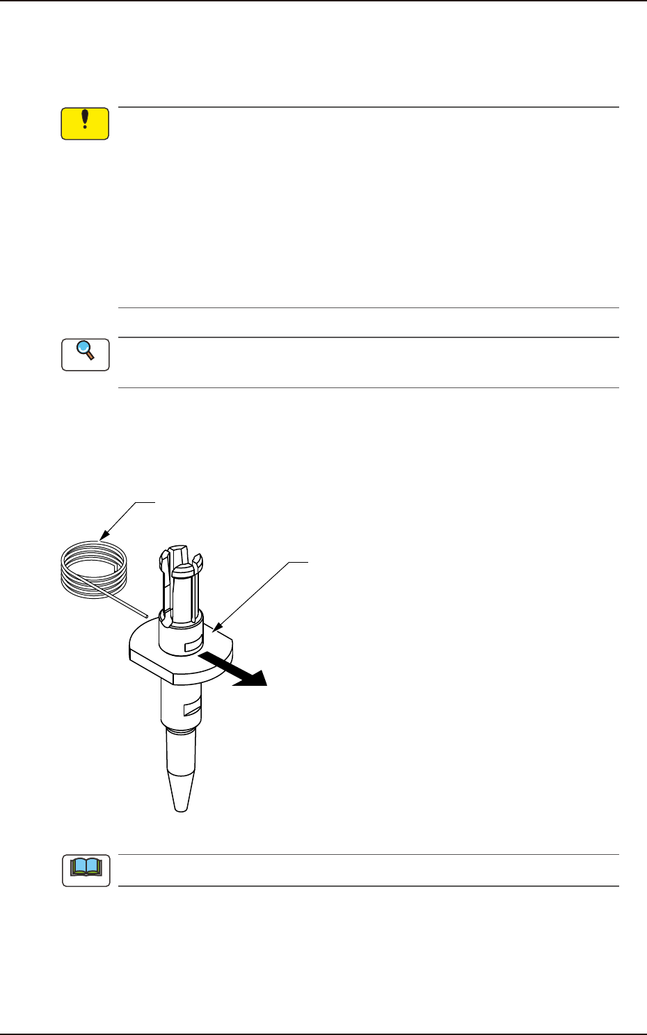
5.3 Nozzle Filter Removal Procedure
Push out the nozzle filter using the filter removal jig as shown in the following figure.
Filter Removing Jig
Vacuum Nozzle
Push
Pushing out the nozzle filter.
F4A48
Do not re-use the removed nozzle filter.
Notice
Reference
Note
EUKYX
1-65199-4100
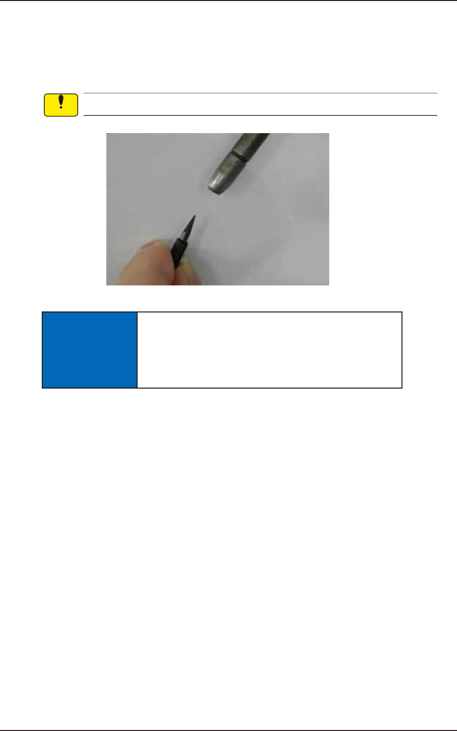
5.4 Method of Blow air
5.4 Method of Blow air
• Remove dust and dirt etc.
Remove slight dust and dirt by blowing air or wiping off.
Clean the tapered area of the vacuum nozzle with a lens cleaning cloth.
Use clean, dry, and non-lubricated air for blowing air.
F4A49
NOTICE
When blowing air to the nozzle, make sure to blow
from the nozzle end section.
If blowing air from the clamp claw section, the clamp
claw might be damaged.
Notice
EUKYX
1-66199-4100
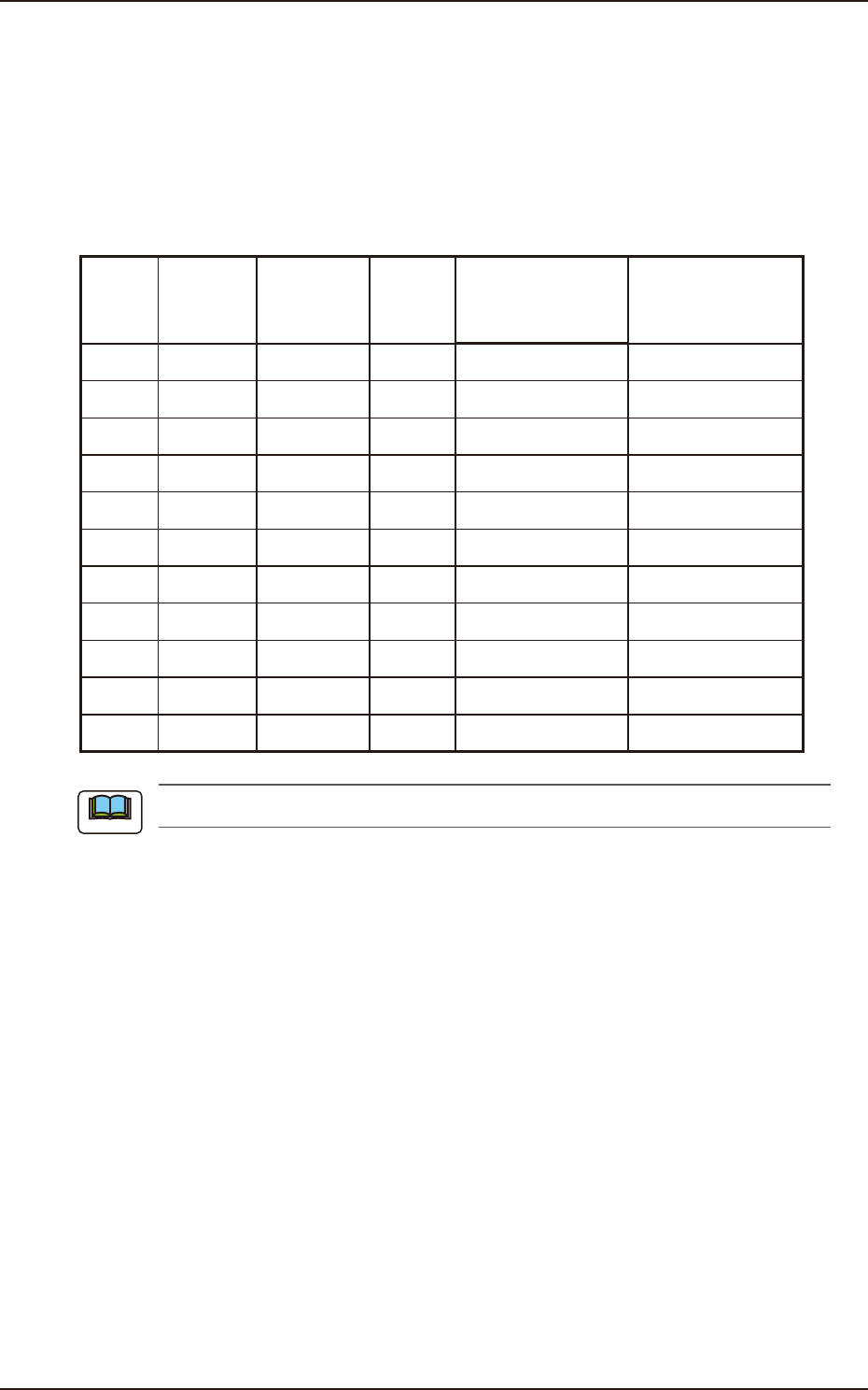
5.5 Cleaning of high-speed nozzle hole part with pin gauge
5.5 Cleaning of high-speed nozzle hole part with pin gauge
Confirm the clog of the nozzle hole with the magnifying glass.
When the clog is found, clean it with the pin gauge.
• Select pin gauge
The pin gauge to be used varies depending on the type of a high-speed nozzle.
Select it referring to the combination shown below.
Unit : mm
Nozzle
ID
Diameter
(center
hole
diameter)
Diameter
(minimum
hole
diameter)
Pin
gauge
size
Part Number
Direction of pin
gauge insertion
HG24C
∅
0.1
∅
0.08
∅
0.08 KYA-M7702-A0 Nail side, Head side
HG33C
∅
0.2
∅
0.08
∅
0.12 K YA-M7703 -A0 Nail side, Head side
HG52C
∅
0.4
∅
0.25
∅
0.2 K YA-M7705 -A0 Nail side, Head side
HG82C
∅
0.7
∅
0.35
∅
0.3 K YA-M7708 -A0 Head side (a)
HV82C
∅
0.7
∅
0.35
∅
0.3 K YA-M7782-A0 Nail side, Head side
HG13C
∅
0.9
∅
0.9
∅
0.6 KYB-M771J-A0 Head side (a)
HV13C
∅
0.9
∅
0.9
∅
0.6 K YA-M7713 -A0 Nail side, Head side
HG14C
∅
1.1
∅
1.1
∅
0.8 KYB-M771K-A0 Head side (a)
HV14C
∅
1.1
∅
1.1
∅
0.8 K YA-M7714-A0 Nail side, Head side
HG15C
∅
2.0
∅
1.1
∅
0.8 KYF-M77G5-A0 Head side (a)
HV15C
∅
2.0
∅
1.1
∅
0.8 K YA-M7715 -A0 Nail side, Head side
(a) Pin gauge can not be inserted from nail side.
Note