EUKYX-199-4110_G5S2_Instruction_Vol4_E.pdf - 第356页
EUKYX 5-8 199-4100 3. T roubleshooting on Placement Errors 3 . T roubl es hooting on Placement Errors 3. 1 Cause and Remedy of Pla cement Error s ( 1 ) Posi tional a nd Angular Deviatio ns of C omponent P l acemen t ( 1 …
EUKYX
5-7199-4100
2.2 Symptom-Based Troubleshooting
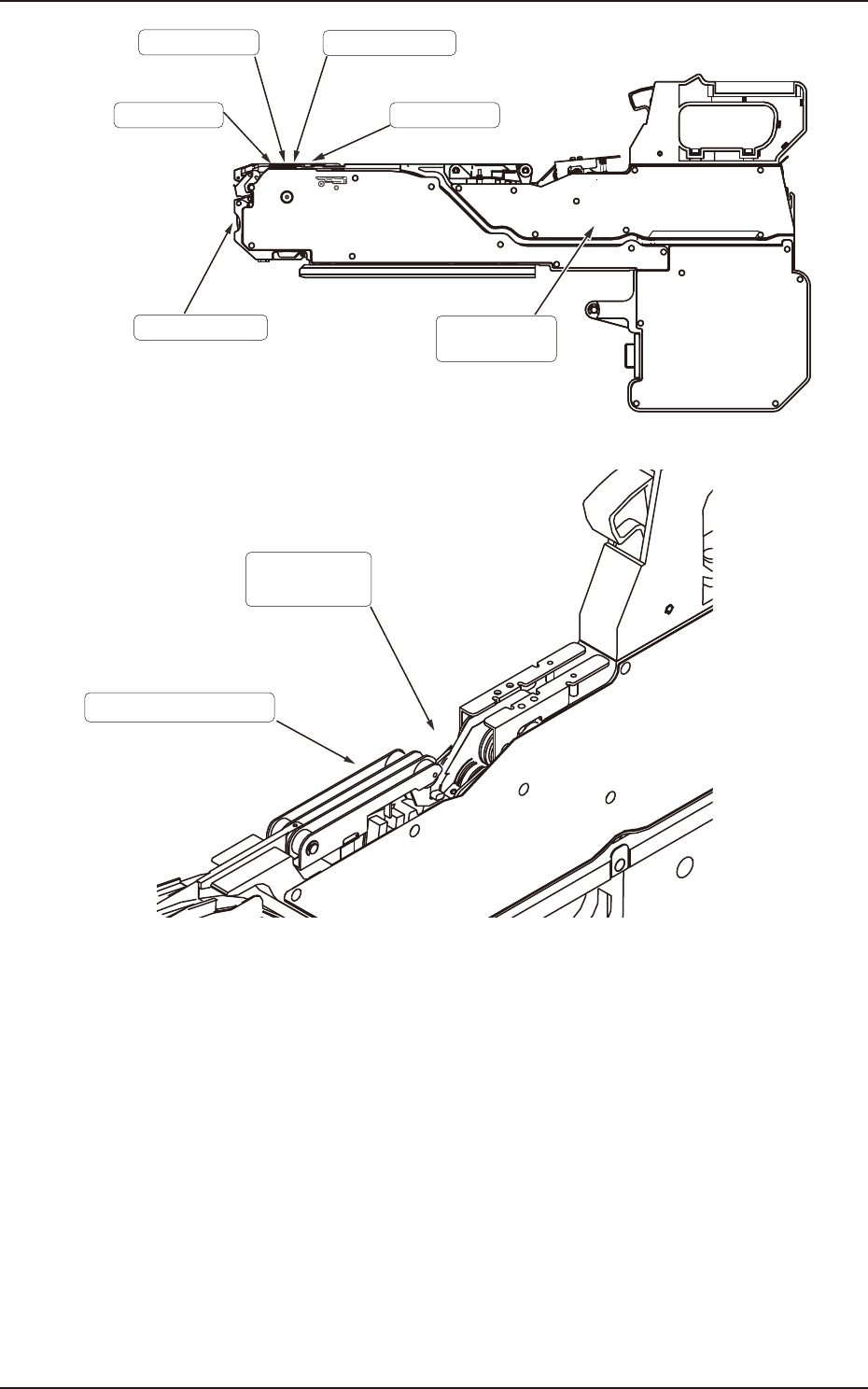
Front Hook
Deformation
Suppressor
Lift/Deformation/
Component adhesion
on inner side
Sprocket
Cover tape/
Take-up gear
Dirt/Component
adhesion
Dirt/Component
adhesion
Pickup Position
Positioning/Positional
deviation
Peeling Area
Gap/Deformation/Dirt
F4E5
Threading of cover tape
Cover tape is set correctly.
Dirt/Component
adhesion
Cover tape/
Take-up gear
F4E6
EUKYX
5-8199-4100
3. Troubleshooting on Placement Errors
3. Troubleshooting on Placement Errors
3.1 Cause and Remedy of Placement Errors
(1) Positional and Angular Deviations of Component Placement
(1-1) Situational Grasp of Error Generation
Positional and angular deviations may be generated in either Process C or D through E. See Fig.
“F4E1”.
By placing a component on the PCB where a double-faced adhesive tape is affixed, it can be
checked and determined in which process positional and angular deviations are generated.
When a positional deviation is generated on the double-faced tape, it indicates that positional and
angular deviations occur in Process C.
When no positional deviation is generated, it means that positional and angular deviations occur in
Process D or E.
(1-2) Positional and Angular Deviations in Process C
When a positional deviation is generated due to the movement of the head after component
recognition or a rotational deviation by placement angle correction, the deviation may be caused
mainly by the following two factors.
• Deterioration of Vacuum Suction Force
• Vibration or Shock during Nozzle (Head) Movement
When one of the above factors exists, unstable components (components that cannot be picked up
in stable condition) such as those shown in “F4E7” are directly affected. When a positional
deviation is generated on the components (the components of the same type that have been used in
the past actual production), check for the above-described factors.
As for vacuum suction force, check the nozzle and the vacuum line.
As for vibration during nozzle movement, check the related spots in the range of Process C.
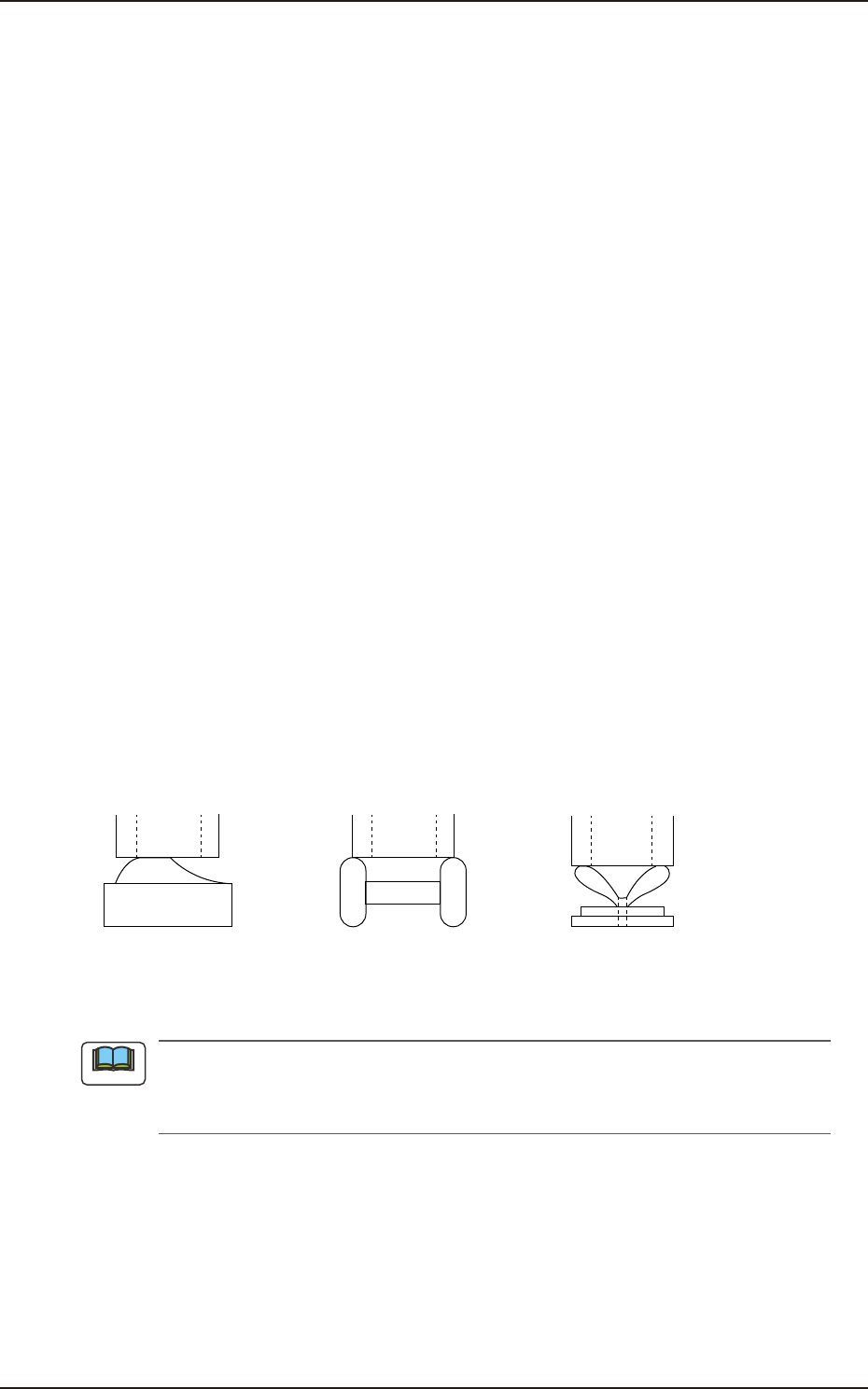
Positional/Angular deviations of component placement (1)
Resistor, Coil, LED, etc.,
with round,protruded, or
smooth upper surface
Capacitor, etc.,
whose electrodes stick out,
causing vacuum leak
Variable resistor, etc.,
that is picked up in
unstable condition
F4E7
When there is a protruding portion on the upper surface of a component, the lower surface of
the vacuum nozzle may be worn out, causing an error during the teaching operation through
component recognition lighting.
Note
EUKYX
5-9199-4100
3.1 Cause and Remedy of Placement Errors
(1-3) Positional or Angular Deviation in Process D through E
When a positional deviation is not generated on the double-faced tape, it indicates that positional
and angular deviations occur in Process D through E.
As a symptom at this time
• The component is dislocated right after it is placed.
• The component is dislocated during operation subsequent to the placement.
• The component is dislocated during PCB discharge operation subsequent to the placement.
The causes in the above cases lie in the factors affected commonly by the shape of the component,
the condition of the PCB, or the condition of solder paste or glue.
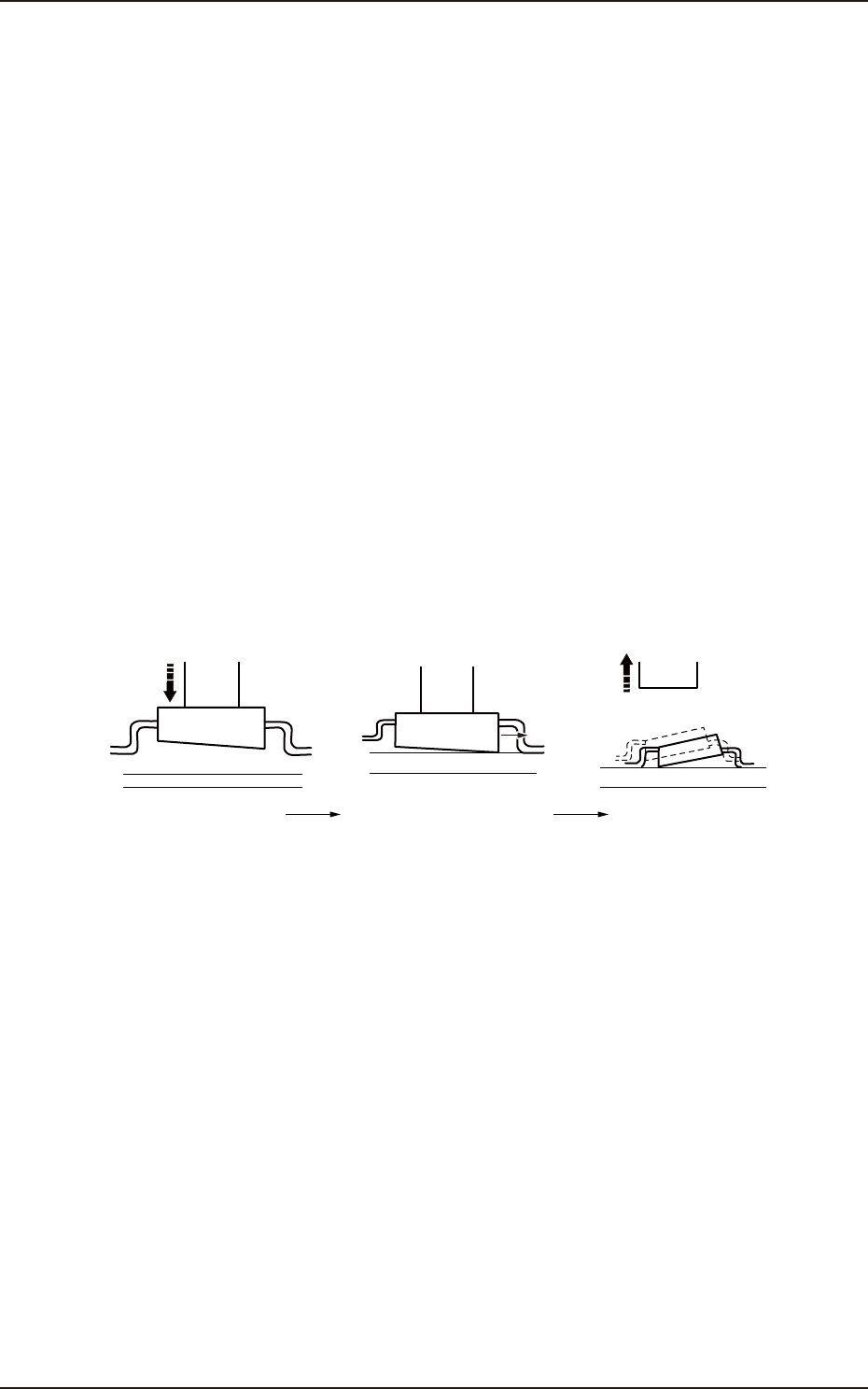
“F4E8” is an example, which shows that a component is dislocated right after it is placed due to the
upper and lower surfaces of the component not parallel to each other.
A force is generated and moves the component in the X direction at the moment when the lower
surface touches the PCB during placement.
This leads to the positional and angular deviations of the component placement.
When this type of component is used, this failure may be avoided by slowing down the placement
speed or slightly increasing the nozzle descent level for the placement.
Some components may be dislocated easily during the backup base movement or a PCB discharge
operation after they are placed.
The factor may be weak holding power of solder paste or glue or imperfect fixation of PCB.
It is required to check these conditions and take individual countermeasures.
Positional/Angular deviations of component placement (2)
Vacuum nozzle
X
Vacuum nozzle is
moved down.
Component shifts in X-direction
during placement.
Positional/Angular deviations
PCB
PCB
F4E8