PCBRM_User_Manual_R9.pdf - 第17页
PCBRM15 & PCBRM System 5.2 User’s Manual Chapter 2: Requirements/Machine Overview Part No. 4005.00.906 2-3 2 Requirements/Machine Overview 2.1 Facility Requirements - PCBRM15 • Physical Dimensions: 32”W x 26”D x 26”H…

PCBRM15 & PCBRM System 5.2 User’s Manual Chapter 2: Requirements/Machine Overview
Part No. 4005.00.906 2-2

PCBRM15 & PCBRM System 5.2 User’s Manual Chapter 2: Requirements/Machine Overview
Part No. 4005.00.906 2-3
2 Requirements/Machine Overview
2.1 Facility Requirements - PCBRM15
• Physical Dimensions: 32”W x 26”D x 26”H
• Maximum Board Size: 22”W x 21”D
• Weight: 125 lbs. (with solder), 90 lbs. (without solder)
• Electrical Requirements:
- Machine (PCBRM15): 208/220VAC, 13 Amps, 50/60 Hz, Single Phase.
Plug = 15 Amp, 250VAC, Nema 6-15P.
- Heater Box (optional): 110/120VAC, 4 Amps, 50/60 Hz, Single Phase.
(PCBRM15)
- Machine (PCBRM15.Z): 208/220VAC, 13 Amps, 50/60Hz, Single Phase.
Plug = Continental Europe 16 Amp
- Heater Box (optional): 208/220VAC, 2 Amps, 50/60Hz, Single Phase
(PCBRM15.Z)
• Compressed Air (optional): 40-80 psi, 2 scfm, clean, moisture-free air (intermittent),
1/8 NPT(M) fitting required.
2.2 Facility Requirements - PCBRM System 5.2
• Max Operating Dimensions: 76”W x 38”D x 28”H
• Weight: 230 lbs. (with solder), 195 lbs. (without solder)
• Electrical Requirements:
- Machine (System 5.2) 208/220 Vac, 45 Amps-full load (overload protected to 55 Amps),
50/60 Hz, single phase, 6 awg 3 wire cord supplied.
- Heater Box (optional): 120 Vac, 4 amps, 50/60 Hz, single phase.
(System 5.2)
- Machine (System 5.2.Z) 208/220 Vac, 15 Amps-full load (overload protected to 20 Amps),
50/60 Hz, 3 phase, 2.5mm
2
x 5 wire cord provided.
- Heater Box (standard): 220 Vac, integral with machine power
(System 5.2.Z)
• Compressed Air (optional): 40-80 psi, 2 scfm, clean, moisture-free air (intermittent),
1/8 NPT(M) fitting required.
Miscellaneous
• 35 lbs. of solder
• Level work area.
• Venting is recommended.
PCBRM15 & PCBRM System 5.2 User’s Manual Chapter 2: Requirements/Machine Overview
Part No. 4005.00.906 2-4
(I) - option
(J)
(C)
(D)
(A)
(H) - option
(B)
(F)
(G)
(B)
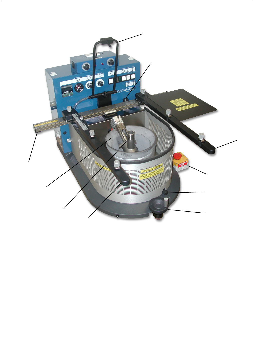
2.3 PCBRM15 - Module Overview
(A) X-Axis Carrier Rail - Cantilever carrier rail adjusts to hold PCB up to 22”W.
(B) PCB Carrier Arms - Carrier arms hold PCB up to 21” deep. PCB Stops with reference scale
provides one time set-up of repetitive assemblies.
(C) X-Axis Carrier Lock - Once PCB is aligned over flow well, the carrier is locked in place.
(D) Z-Axis Height Adjustment - Adjusts height of PCB in relation to the flow well.
(F) Solder Pot
(G) Solder Pump
(H) APS System- Blows low pressure air through holes in PCB of removed component to clear them of
solder.
(I) APS System Air Regulator – Sets air pressure.
(J) Emergency Stop – Shuts system down immediately if required.