PCBRM_User_Manual_R9.pdf - 第75页
Pcbrm15 & PCBRM System 5.2 User’s Manual Chapter 5: Maintenance/Parts Part No. 4005.00.906 5- 7 5.3.1 Replacement of Pump Bearings: • Follow all the steps outlined in Pump Disassembly. • After Impeller and Shaft Asse…
Pcbrm15 & PCBRM System 5.2 User’s Manual Chapter 5: Maintenance/Parts
Part No. 4005.00.906 5-6
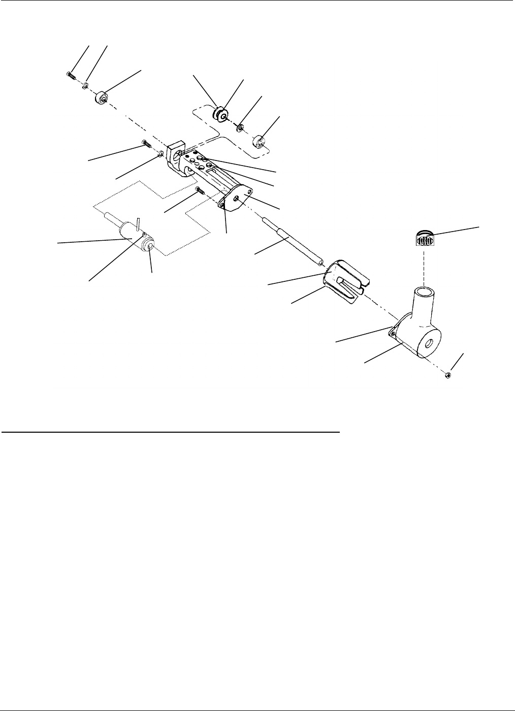
Item Description Qty. Part# (PCBRM15)
- Pump Assembly-PCBRM15 1 2004.01.044
A Pump Bracket 1 2004.01.102 (gray iron)
B Pump Housing 1 2004.01.101 (gray iron)
C Pump Impeller 1 2004.01.100 (gray iron)
D Shaft 1 2004.01.103 (titanium)
E Bearing 2 9001.09.020
F Spacer 1 12464
G Pulley 1 12453
H Screw, 6-32 x 1/4 Button Hd 2 60A
I Washer, #6 SAE 2 9A
J Screw, 10-32 x 5/8 2 9000.00.000 (titanium)
K Nut, 10-32 2 9000.06.002 (titanium)
L Nut, 6-32 x 4 8B
M Set Screw, 6-32 x 5/16 4 11A
N Pump Sleeve Assembly 1 2004.01.041 (titanium)
O Set Screw, 10-32 x 3/8 1 9000.10.249 (titanium)
P Baffle Assembly 1 2004.01.043 (titanium)
Q Pump Mounting screws (10-32 x _) 2 23A
R Pump Insert 1 12418
H
I
E
G
F
E
M
L
A
H
I
J
N
Index Mark
D
C
B
K
upper
HUB
This side
Index Mark
O
P
.
NOTE 1:
When cleaning of pump is required, the pump shaft (D) and the
pump sleeve insert (R) need to be replaced.
R
See note 1
See note 1
9000.02.000
Pcbrm15 & PCBRM System 5.2 User’s Manual Chapter 5: Maintenance/Parts
Part No. 4005.00.906 5-7
5.3.1 Replacement of Pump Bearings:
• Follow all the steps outlined in Pump Disassembly.
• After Impeller and Shaft Assembly are removed, the Impeller Pulley, Bearing Spacer, and
Lower Bearing can be removed.
• Remove Bearing Retainer Hex Screw and Washer, allowing removal of Upper Bearing.
• Use graphite lubricant on screws.
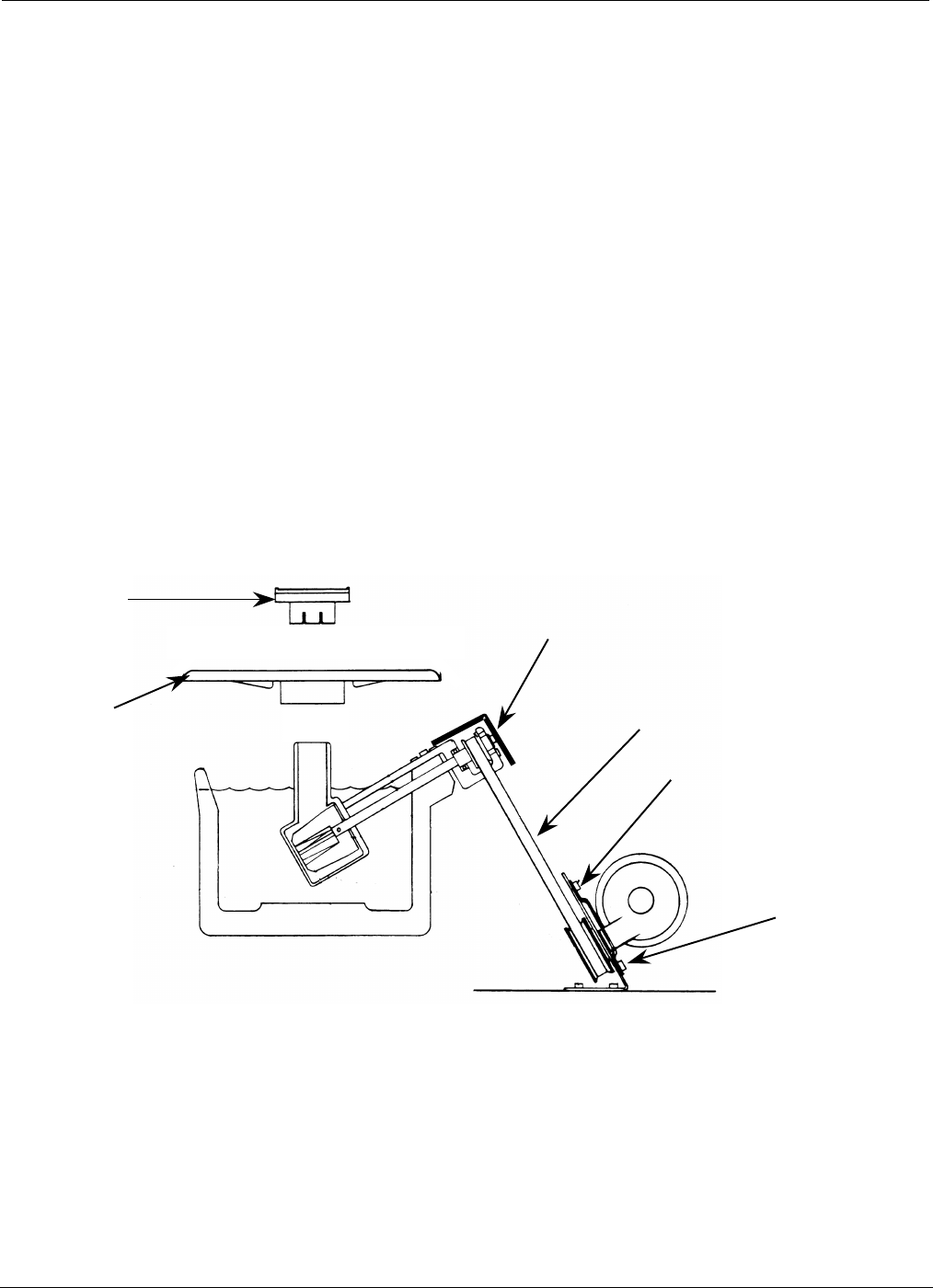
5.3.2 Replacement of Drive Belt (A):
• Disconnect electrical power.
• Remove Rear Cover Screws (4).
• Remove Flow Well (B) & Pot Cover (C).
• Remove Belt Guard Hex Screws (2) and Belt Guard (D).
• Loosen Screws (4) holding Motor (E). Slide motor as high as possible.
• Remove Drive Belt (A).
• Replace Drive Belt and reassemble.
(D)
(A)
(E)
(B)
(C)
(E)
Pcbrm15 & PCBRM System 5.2 User’s Manual Chapter 5: Maintenance/Parts
Part No. 4005.00.906 5-8
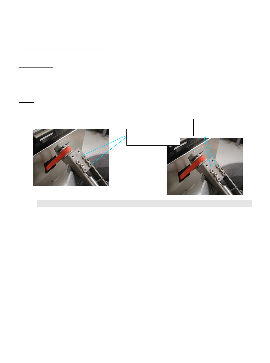
5.4 Pump Leveling
Carrier Arms Parallel Solder Pump:
Tools Needed:
− 1/16” Allen wrench,
− 5/16” Cresent wrench,
− Bubble level
Steps:
• Mount the pump onto the solder pot and snug the mounting screws. DO NOT OVER TIGHTEN.
• Bring to bear the (4) leveling screws leaving the lock nuts loose.
Note:
WHEN ADJUSTING THE PUMP, THE TWO MOUNTING SCREWS NEED TO BE LOOSENED PRIOR TO
MAKING ADJUSTMENTS TO ANY OF THE LEVELING SCREWS. THEN, SNUG BACK DOWN TO READ
THE LEVEL. TWO LEVELING SCREWS NEED TO BE ADJUSTED IN ANY ONE ADJUSTMENT.
EXAMPLE – WHEN PARALLELING THE PUMP TO THE CARRIER ARMS, EITHER THE RIGHT TWO
SCREWS WILL BE ADJUSTED TOGETHER, OR THE LEFT TWO SCREWS TOGETHER FOR
EAST/WEST ADJUSTMENT. AND THE BOTTOM TWO SCREWS WILL BE ADJUSTED
TOGETHER OR THE TOP TWO SCREWS FOR NORTH/SOUTH ADJUSTMENT IT IS ALSO
VERY CRITICAL TO ADJUST BOTH SCREWS EXACTLY THE SAME AMOUNT.
Right two leveling
screws and lock nuts
Top two leveling screws and
lock nuts