PCBRM_User_Manual_R9.pdf - 第60页
PCBRM15 & PCBRM System 5. 2 User’s Manual Chapter 4: Process es & Appl icati ons Part No. 4005.00.906 4- 18 9. Move PCB in the Y - Axis and align component/lead pattern over the flow well. Use the APS over arm an…
PCBRM15 & PCBRM System 5.2 User’s Manual
Chapter 4: Processes & Applications
Part No. 4005.00.906 4-17
Z-Axis
Positioning Knob
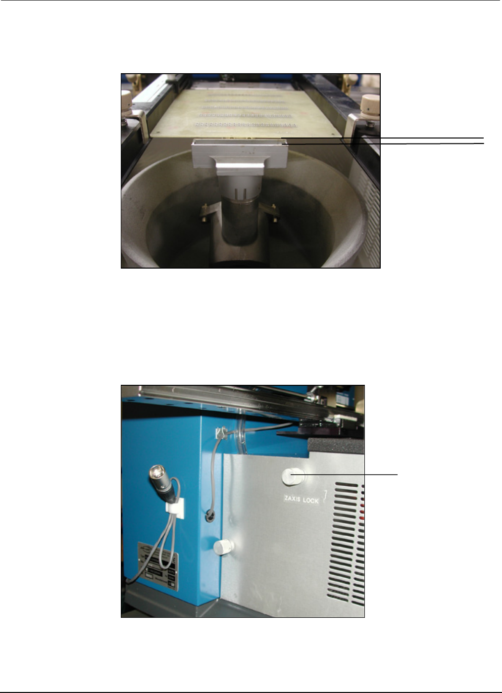
8. Raise Z-Axis using Z-Axis height adjustment wheel and adjust PCB to a height of 1/16” above the
flow well.
• For System 5.2, loosen Z-Axis lock knob and then tighten. The Z-Axis height is now set for
repetitive applications.
1/16”
PCBRM15 & PCBRM System 5.2 User’s Manual
Chapter 4: Processes & Applications
Part No. 4005.00.906 4-18
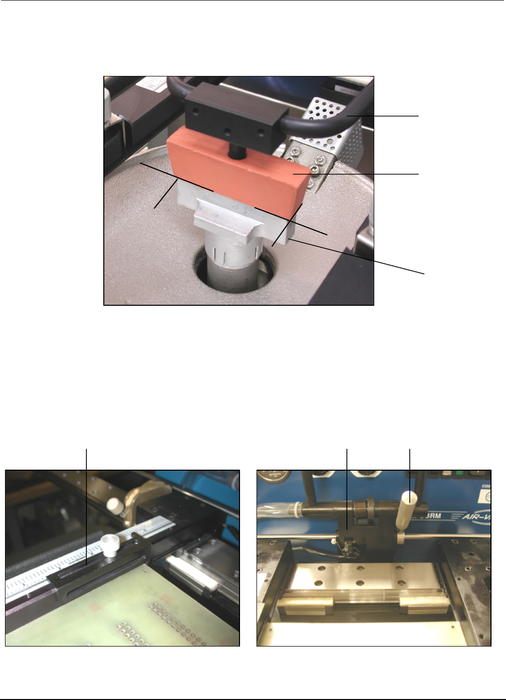
9. Move PCB in the Y-Axis and align component/lead pattern over the flow well. Use the APS over arm
and cleaning hood to locate, if so equipped. Lock the X-Axis carrier lock.
10. Adjust the Y-Axis stop to set position of PCB in the carrier arms.
• For System 5.2, move the right X-Axis lock to the left until hand stop against center bracket.
APS
Overarm
Cleaning
Hood
Flow
Well
Y-Axis PCB Stop
Center Bracket
X-Axis Lock
PCBRM15 & PCBRM System 5.2 User’s Manual
Chapter 4: Processes & Applications
Part No. 4005.00.906 4-19
X-Axis
Carrier Lock
Z-Axis
Adjustment Wheel
11. Remove PCB from carrier arms.
• For System 5.2, unlock X-Axis carrier lock.
12. Turn on machine and let temperature stabilize. Adjust temperature as required.
• For System 5.2 turn on preheater. Adjust temperature as required.
Note
ALWAYS HEAT SOAK FLOW WELLS FOR A MINIMUM OF 15 MINUTES BEFORE FLOWING SOLDER.
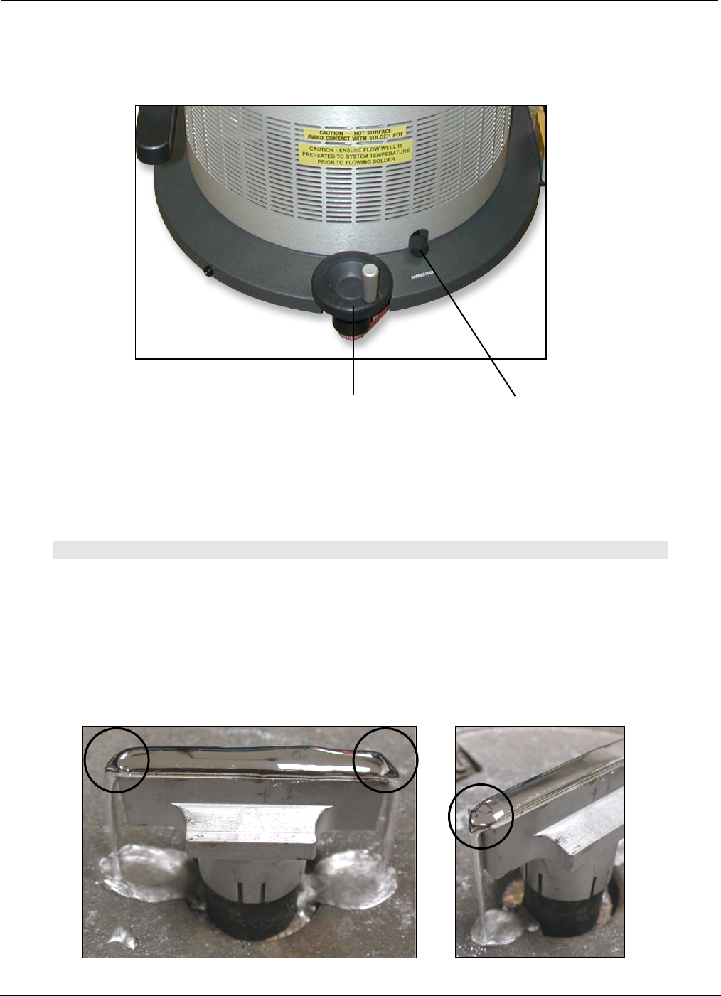
13. Set solder flow rate. Starting at zero, set mode switch to continuous.
14. Slowly increase flow rate until solder flows off the edge(s) of the flow well. Flow rate is now set for
that flow well. Different flow rate is required for different size flow wells.
Solder Flow