PCBRM_User_Manual_R9.pdf - 第29页
PCBRM15 & PCBRM System 5.2 User’s Manual Chapter 3: Set Up & Installation Part No. 4005.00.906 3-3 3 Set Up & Installation 3.1 Leveling Module CAUTION: O PERATION OF THIS MODULE INVOLVES PUMPING OF MOLTEN SOL…

PCBRM15 & PCBRM System 5.2 User’s Manual Chapter 3: Set Up & Installation
Part No. 4005.00.906 3-2
PCBRM15 & PCBRM System 5.2 User’s Manual Chapter 3: Set Up & Installation
Part No. 4005.00.906 3-3
3 Set Up & Installation
3.1 Leveling Module
CAUTION:
OPERATION OF THIS MODULE INVOLVES PUMPING OF MOLTEN SOLDER. ALL NORMAL SAFETY
PRACTICES SHOULD BE OBSERVED WITH SPECIAL ATTENTION TO THE FOLLOWING:
SAFETY GLASSES SHOULD BE WORN AT ALL TIMES.
DO NOT MOVE MODULE WHILE SOLDER IS MOLTEN.
DISCONNECT POWER BEFORE SERVICING MODULES.
CAUTION:
LEVELING OF MODULE SHOULD NOT BE ATTEMPTED WITH MOLTEN SOLDER IN THE POT.
Note:
LEVELING IS CRITICAL TO PROVIDE CORRECT SOLDER FLOW.
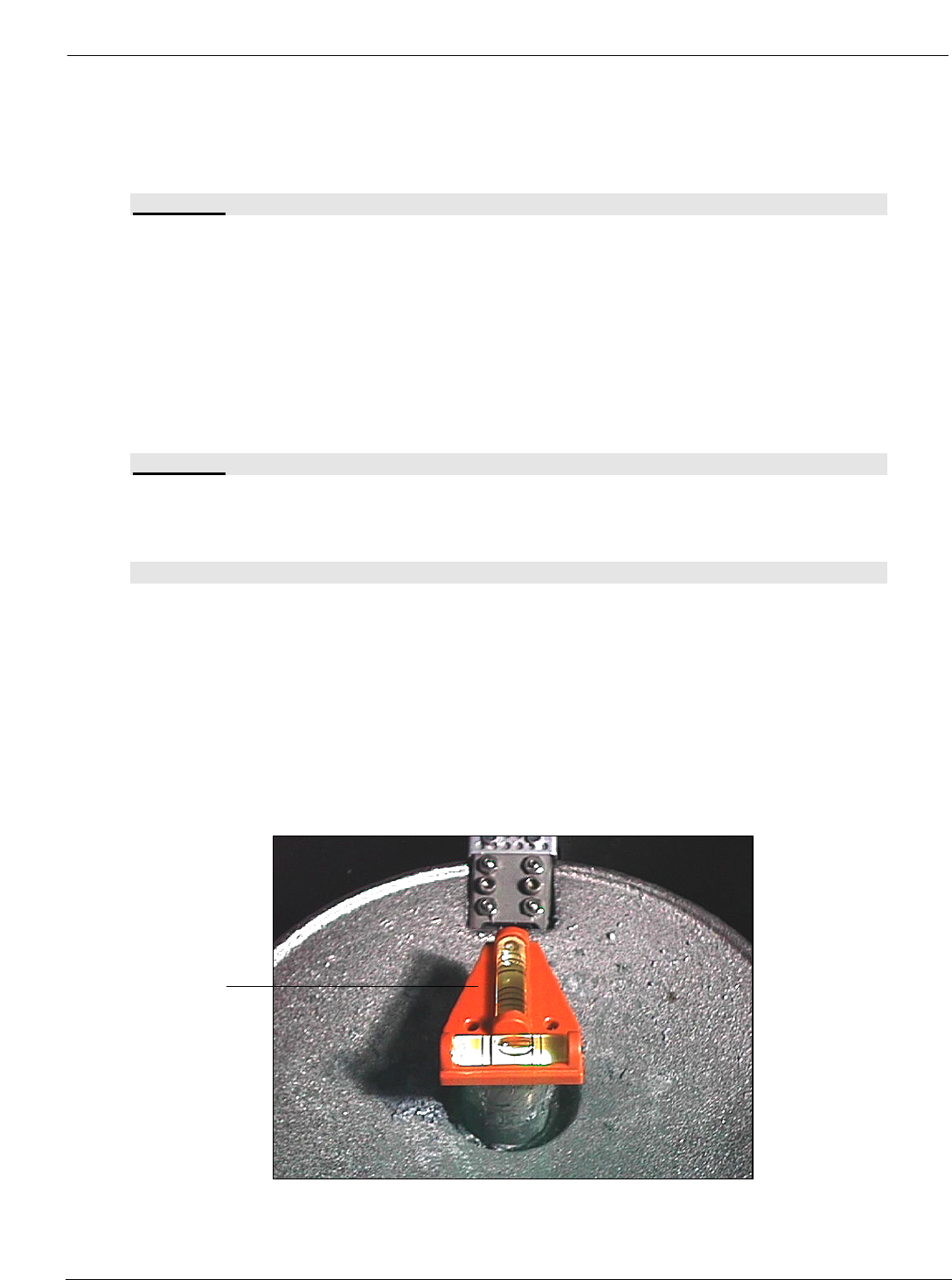
• Level machine on table.
• Place the level (supplied with tool kit) on Pump Housing (A). Level machine (front to back and
side to side) by adjusting the Leveling Legs.
• After leveling is completed, lock legs with jam nuts.
(A)
PCBRM15 & PCBRM System 5.2 User’s Manual Chapter 3: Set Up & Installation
Part No. 4005.00.906 3-4
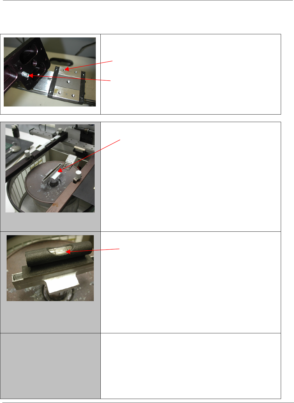
3.2 PCBRM15 – Carrier Arms Installation
• Install right and left carrier arms to the bearing block
using the M4 screws supplied.
• When installing the arms, please note that the spring
must be installed as shown.
1. Start with a flow well installed on the solder pump.
2. Place a level on the flow well and note level of the
well.