PCBRM_User_Manual_R9.pdf - 第87页
Pcbrm15 & PCBRM Syst em 5.2 User ’s Manual Chapter 6: Troubl eshootin g Part No. 4005.00.906 6- 1 6: Troubleshooting 6 Troubleshooting .................................................................................…
Pcbrm15 & PCBRM System 5.2 User’s Manual Chapter 5: Maintenance/Parts
Part No. 4005.00.906 5-18
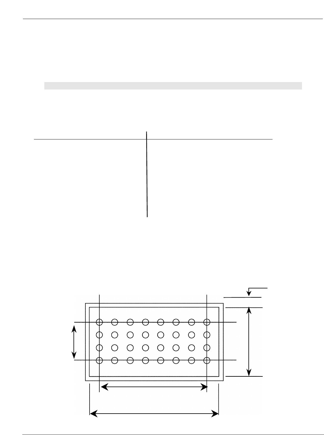
Component
width
Flow Well
width
Component length
Flow Well length
.055 (TYP)
5.9.3 Standard Flow Wells & Air Cleaning Hoods
The flow well must be larger than the component lead pattern to insure that all leads are within the
solder wave. Generally an edge distance of 1/16” is added around the lead pattern and on long
connectors where heat dissipates at the end of the well, an edge distance of 3/16” is recommended.
Note:
NORMALLY CLEANING HOOD DIMENSIONS ARE THE SAME AS FLOW WELL DIMENSIONS. WHERE
DENSITY AND/OR ADJACENT COMPONENT CONFIGURATIONS PRESENT AN INTERFERENCE
PROBLEM, HOODS CAN BE MODIFIED TO MORE CLOSELY CONFORM TO LEAD PATTERNS.
Dimension Flow Well Dimension Flow Well
(W” x L”) Part Number (W” x L”) Part Number
1/4 x 1 1/4 FW8-40 7/8 x 1 5/8 FW28-52
3/8 x 1 3/8 FW12-44 1 x 1 7/16 FW32-46
3/8 x 2 3/16 FW12-70 1 1/8 x 1 1/8 FW36-36
3/8 x 2 3/4 FW12-88 1 1/4 x 1 1/4 FW40-40
3/8 x 3 1/4 FW12-104 1 3/8 x 1 3/8 FW44-44
_ x 29/32 FW16-29 1 _ x 1 _ FW48-48
_ x 1 FW16-32 1 3/4 x 1 3/4 FW56-56
3/4 x 1 5/16 FW24-42 2 x 2 FW64-64
3/4 x 1 _ FW24-48 1/4 x 4 FW8-128
3/4 x 2 FW24-64 3/8 x 5 FW12-160
3/4 x 2 3/16 FW24-70 _ x 5 FW16-160
3/4 x 2 _ FW24-80
Flow Well Sizing
• The size is basically determined by the component pin centerline distances.
• The contact area must include every lead of the pattern to be contacted by flowing solder. The
length and width dimensions must provide generous heat contact and ease for operator
component positioning.

Pcbrm15 & PCBRM System 5.2 User’s Manual Chapter 6: Troubleshooting
Part No. 4005.00.906 6-1
6: Troubleshooting
6 Troubleshooting .................................................................................................................................. 3
6.0 Air-Vac Technical Service ....................................................................................................................... 3
6.1 Common Problems/Solutions .................................................................................................................. 3
6.2 Temperature Controller Installation (CAL 9900 only) ......................................................................... 5

Pcbrm15 & PCBRM System 5.2 User’s Manual Chapter 6: Troubleshooting
Part No. 4005.00.906 6-2