PCBRM_User_Manual_R9.pdf - 第33页
PCBRM15 & PCBRM System 5.2 User’s Manual Chapter 3: Set Up & Installation Part No. 4005.00.906 3-7 Compliant (carrier) Arm Lock Assembly Carrier Arm 3.3 PCBRM System 5.2 - Carrier Arms Installation • Loosen lock …
PCBRM15 & PCBRM System 5.2 User’s Manual Chapter 3: Set Up & Installation
Part No. 4005.00.906 3-6
6. Loosen the rear two screws of each arm _ turn.
7. Turn the adjustment screw clockwise on both arms
equally an 1/8 of a turn at a time until the level is at
the desired place.
8. Once level is achieved, bring the rear two screws
to bare only. Make a final adjustment as required
and bring the front screws to bare. Now snug up all
the screws – Do Not Over tighten.
PCBRM15 & PCBRM System 5.2 User’s Manual Chapter 3: Set Up & Installation
Part No. 4005.00.906 3-7
Compliant
(carrier) Arm
Lock Assembly
Carrier Arm
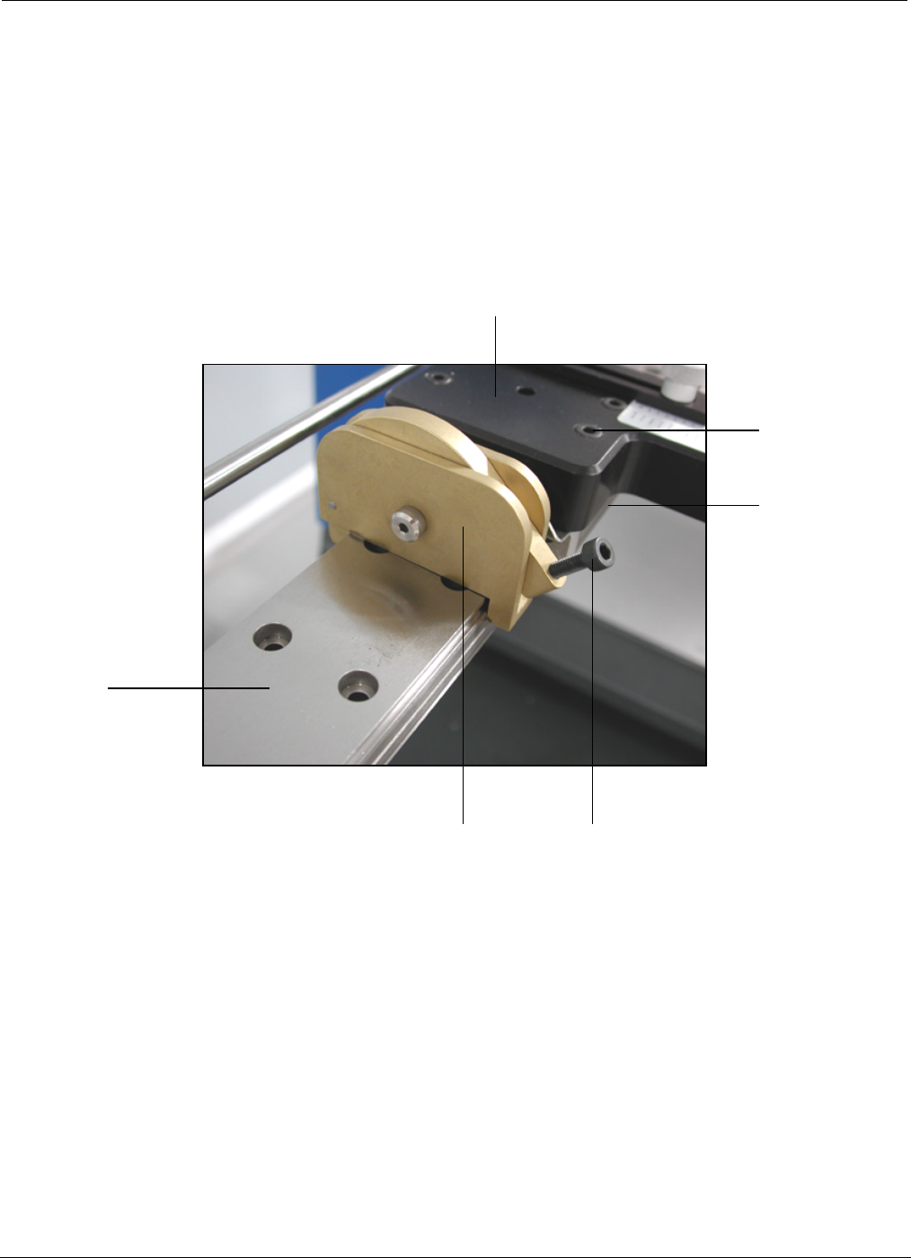
3.3 PCBRM System 5.2 - Carrier Arms Installation
• Loosen lock knob so compliant (carrier) arm lock assembly can straddle the x-axis rail.
• Place compliant arm lock assembly in place, as shown.
• Use mounting screws to mount carrier arm to bearing block.
Lock Knob
Bearing
Block
Mounting
Screw
X-Axis
Rail
PCBRM15 & PCBRM System 5.2 User’s Manual Chapter 3: Set Up & Installation
Part No. 4005.00.906 3-8
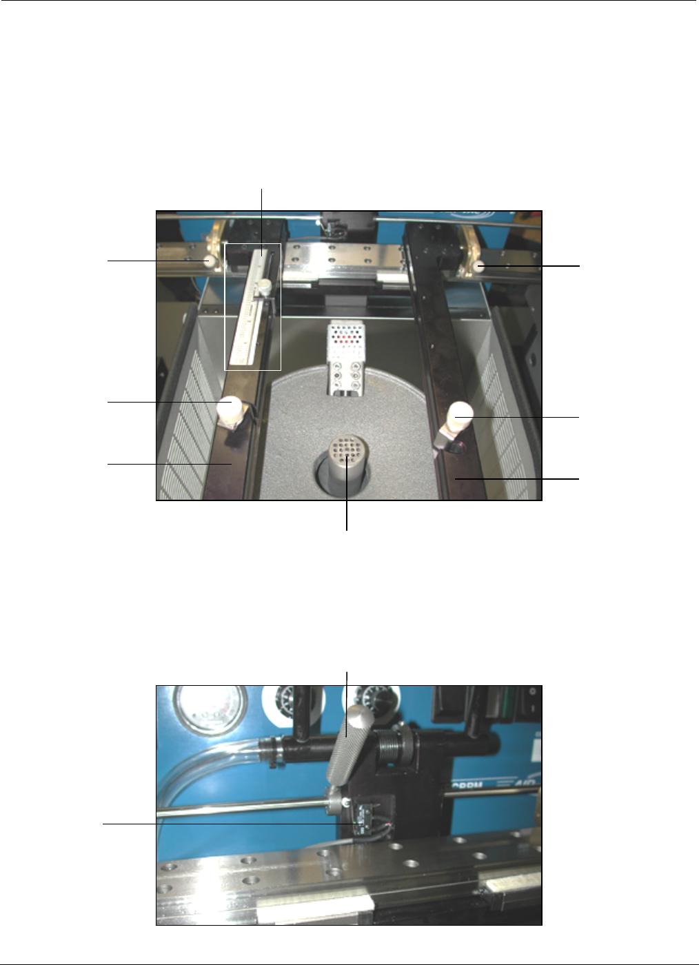
Compliant Arm Lock
Temperature
Monitor
Activation
Switch
Solder Baffle
Compliant
Arm Lock
Knobs
Y-Axis Stop and Scale
Compliant
Arm Lock
Knobs
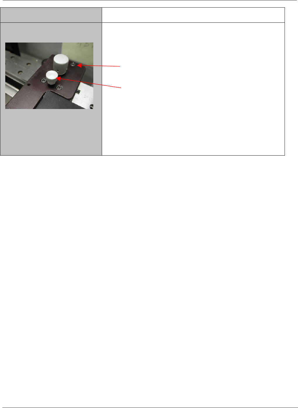
Board
Lock Knobs
Carrier
Arms
Board
Lock Knobs
Carrier
Arms
3.4 PCBRM System 5.2 – X Axis Stops, Set Up, Function
• Locate PCB in carrier arms and lock arms in place using compliant arm lock knobs.
• Locate PCB in the y-axis and set stop.
• Lock PCB in arms using board lock knobs.
• Set x-axis stop (preheater) once PCB has been located in the preheater.