PCBRM_User_Manual_R9.pdf - 第47页
PCBRM15 & PCBRM System 5. 2 User’s Manual Chapter 4: Process es & Appl icati ons Part No. 4005.00.906 4-5 Flow Well Heater Heater Control Box Note Routing Of Heater Cable • Connect flow well heate rs to power, if…
PCBRM15 & PCBRM System 5.2 User’s Manual
Chapter 4: Processes & Applications
Part No. 4005.00.906 4-4
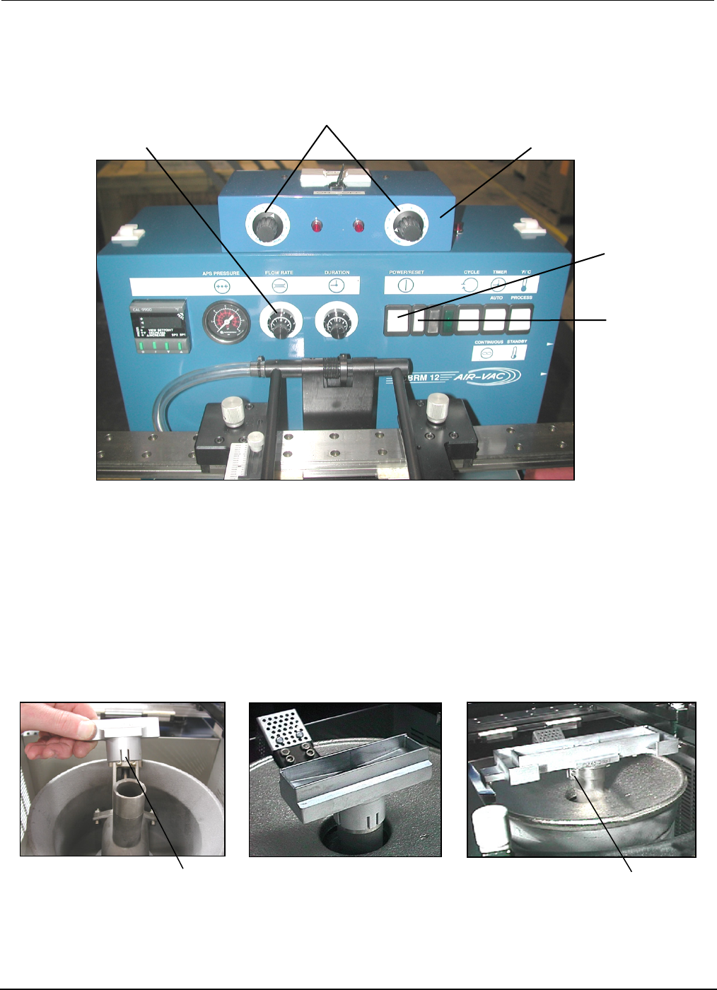
Main Power
Reset Switch
Solder Flow Rate Control
Hi/Low Flow Well Heater Adjust
Flow Well Heater Box
Spring Tabs
Screw
1
2
3
4.2 Flow Well Set-Up
• Push the Main Power and Reset Switches. Process temperature is factory set at 500˚F (adjust as
required).
• Using insulated gloves, push down on flow well and insure it is completely seated on pump. If
required, adjust Spring Tabs of well or tighten Clampable Shank (screw) as required to insure flow
well maintains firmly positioned on pump.
PCBRM15 & PCBRM System 5.2 User’s Manual
Chapter 4: Processes & Applications
Part No. 4005.00.906 4-5
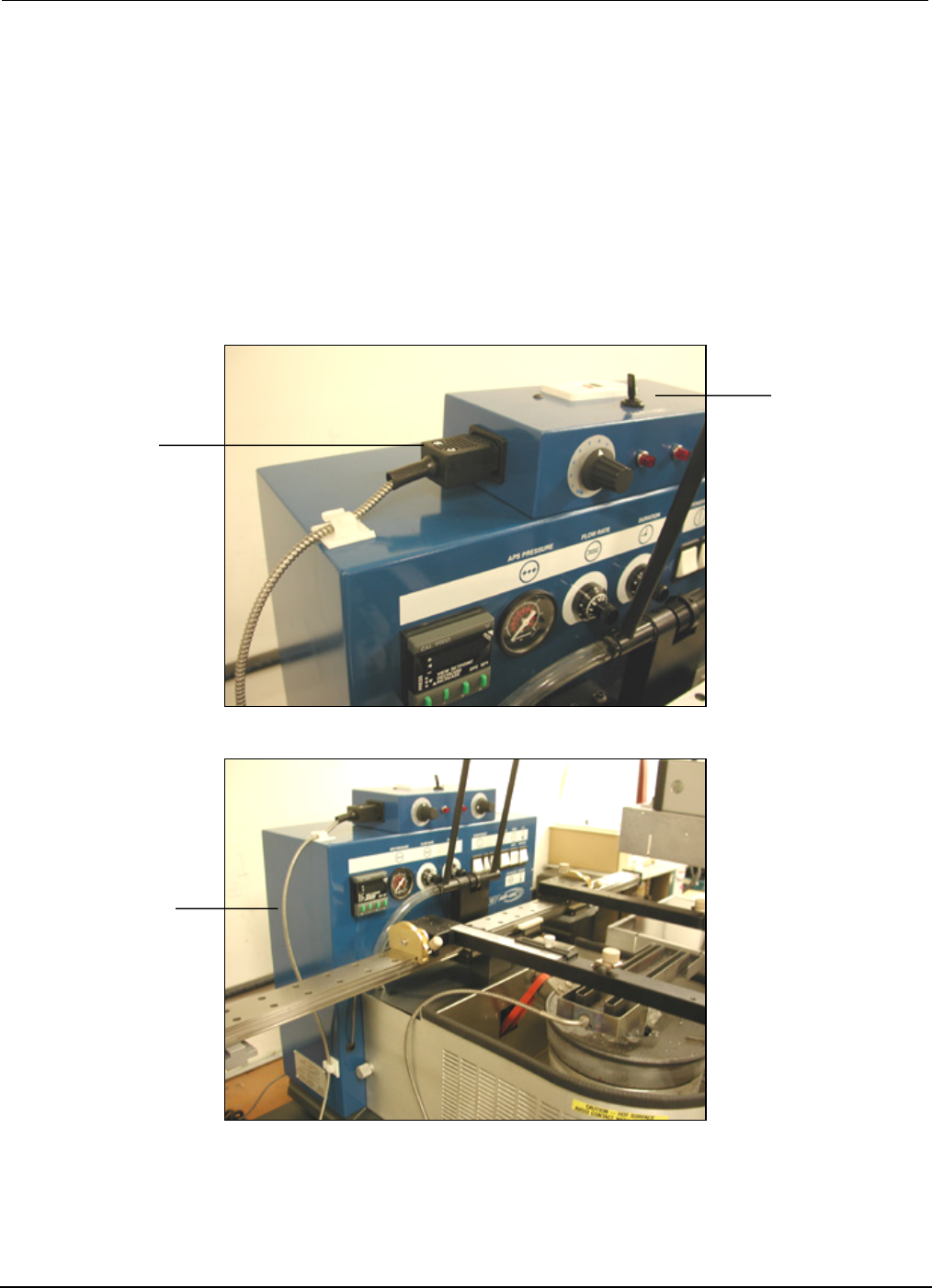
Flow Well
Heater
Heater
Control Box
Note Routing
Of Heater Cable
• Connect flow well heaters to power, if applicable. Adjust heaters as required.
• Allow machine to reach and stabilize temperature—typically 45 minutes.
• After flow well has heat soaked for 15 minutes, set Solder Flow Rate Control to zero. Mode Switch
and Cycle Machine set to Continuous. Slowly increase Solder Flow Rate Control until solder fills the
flow well and starts flowing over the ends.
• Solder may solidify in flow well if not heat soaked. Do not increase flow rate. Allow flow well to
heat soak further.
• Select Mode Switch to Off position (center).
PCBRM15 & PCBRM System 5.2 User’s Manual
Chapter 4: Processes & Applications
Part No. 4005.00.906 4-6
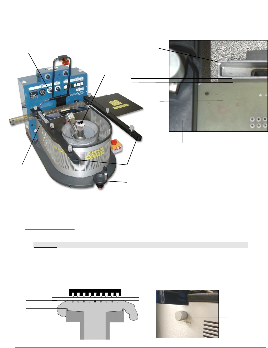
Flow Well
Carrier Arms
Z-Height Adjustment Wheel
Flow Well
parallel
PCB
Solder Flow Rate Control
Carrier Arm
(A)
(A)
•
• Using the Z-Axis Height Adjustment Wheel, lower carrier to allow Carrier Arms to touch side of Flow
Well.
• Adjust Flow Well parallel to carrier arms or use edge of a pcb as a guide to square the flow well as
shown in photo.
Adjusting PCB Height:
• A space of approximately 1/16” between the top of the flow well and the bottom of the pcb. Molten
solder needs to flow through this space, contact all leads and flow freely back into the solder pot.
Use Z-height adjustment wheel to adjust.
• PCBRM System 5.2 – Once height is set, loosen and then lock the z-height adjust (A). Once set,
unit is set for repetative processes.
CAUTION:
INSUFFICIENT CLEARANCE COULD FORCE THE SOLDER TO FLOW UP THROUGH THE BARRELS
OF THE BOARD AND FLOOD THE TOP OF THE BOARD. IT COULD ALSO CREATE A SAFETY
CONCERN FOCING SOLDER UNDER PRESSURE OUT OF NARROW FLOW WELL/PCB
OPENINGS.SOLDER CAN DEFLECT ALONG THE BOTTOM OF THE PCB TO ADJACENT AREAS.
Bottom of
PCB
Top of
Flow Well
1/16”