PCBRM_User_Manual_R9.pdf - 第90页
Pcbrm15 & PCBRM Syst em 5.2 User ’s Manual Chapter 6: Troubl eshootin g Part No. 4005.00.906 6- 4 6.1.3 Poor Solder Re sults 1. Un - lev el pump ( see leveling procedure). 2. Un - lev el machine (see leveling procedu…

Pcbrm15 & PCBRM System 5.2 User’s Manual Chapter 6: Troubleshooting
Part No. 4005.00.906 6-3
6 Troubleshooting
6.0 Air-Vac Technical Service
Air-Vac is always willing to assist our customers with any technical or operating questions. If you have
any questions on machine parameters, correct nozzle requirements, options, procedures or
maintenance, please do not hesitate to call.
Air-Vac Engineering Company, Inc.
30 Progress Avenue • Seymour, CT 06483 • Tel: 203-888-9900 • Fax: 203-888-1145
www.air-vac-eng.com
e-mail:
General Sales Information: rework.sales@air-vac-eng.com
Technical Support: rework.tech@air-vac-eng.com
6.1 Common Problems/Solutions
NOTE
ALL PCBRM UNITS ARE TESTED PRIOR TO SHIPPING. TEMPERATURE CONTROLLERS ARE
PROGRAMMED AND TESTED AT 500°F/260°C.
6.1.1 Machine will not turn on, or turns on for a short period and shuts off
1. Defective latching relay 12879.
2. Consult Air-Vac for further help.
6.1.2 Pump Motor will not run
1. Motor fuse blown
WARNING
DO NOT REPLACE MOTOR FUSE WITH ANY OTHER FUSE BESIDES 250V3AG, 3/10 AMP.
INCORRECT FUSING CAN RESULT IN DAMAGE TO SYSTEM. IF MOTOR FUSE STARTS TO BLOW
CONTINUOUSLY, SOLDER PUMP NEEDS TO BE REMOVED, DISASSEMBLED AND THOROUGHLY
CLEANED.
2. Footswitch not plugged in.
3. SP2 – activated on temperature controller – see 0 #’s 3-5.
4. Stand-by switch activated.
5. Pump seized.
6. Set point temperature set too low – solder not molten.
7. Consult Air-Vac for further help.

Pcbrm15 & PCBRM System 5.2 User’s Manual Chapter 6: Troubleshooting
Part No. 4005.00.906 6-4
6.1.3 Poor Solder Results
1. Un-level pump (see leveling procedure).
2. Un-level machine (see leveling procedure).
3. Z-Axis height not set correctly.
4. Baffle not being used.
5. Flow duration not set correctly.
6. Ramp up/down not set correctly.
7. Consult Air-Vac for further help.
6.1.4 Excessive Fluctuation of Solder Wave
1. Replace motor belt.
2. Motor belt tension too tight.
3. Solder pump needs to be removed from pot, disassembled and thoroughly cleaned.
4. Consult Air-Vac for further help.
6.1.5 Fault Indication (CAL9900 only)
Temperature display, on a fault indication, is replaced by “EE” flashing, followed by a digit. This indicates
that an error has been detected in the system. Action should be taken as follows:
EE1 – SENSOR BURNOUT – CHECK SENSOR AND/OR CONNECTIONS THEN KEY*
EE2 – TEMPORARY SYSTEM ERROR SELF CLEANING
EE8 – LOSS OF CALIBRATION
EE9 – NVM DATA FAULT (NON VOLATILE MEMORY)
Note: Repair & Re-Calibration
DUE TO THE NATURE OF ITS DESIGN, THE 9900 CAN ONLY BE REPAIRED AND RE-CALIBRATED
BY USING SPECIAL EQUIPMENT AND SHOULD BE RETURNED TO AIR-VAC IF FOUND TO BE
FAULTY.
Note
TO RESET EE9 FAULT (CAUSED BY SPIKING), TURN OFF MACHINE, PRESS “P” IN AND TURN ON
POWER UNTIL DISPLAY COMES ON LINE. PARAMETER LOCK NEEDS TO BE IN THE SETTING
POSITION.
Pcbrm15 & PCBRM System 5.2 User’s Manual Chapter 6: Troubleshooting
Part No. 4005.00.906 6-5
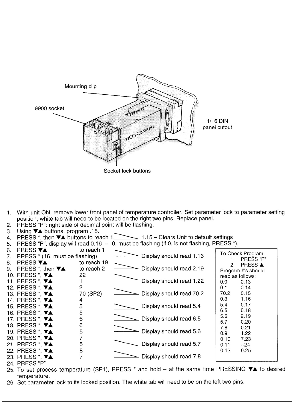
6.2 Temperature Controller Installation (CAL 9900 only)
1. Remove the socket by pressing in the lock buttons.
2. Slide the controller into the cut-out.
3. Fit the mounting clip by pressing it firmly against the panel, jacking screws optional.
4. Plug on the socket.
6.2.1 Setting Parameters of the CAL 9900 Temp Controller (also refer to Cal control booklet)