PCBRM_User_Manual_R9.pdf - 第62页
PCBRM15 & PCBRM System 5. 2 User’s Manual Chapter 4: Process es & Appl icati ons Part No. 4005.00.906 4- 20 15. Set mode switch to auto (top) position. 16. Pla ce PCB in carrier arms and lock in place with the bo…
PCBRM15 & PCBRM System 5.2 User’s Manual
Chapter 4: Processes & Applications
Part No. 4005.00.906 4-19
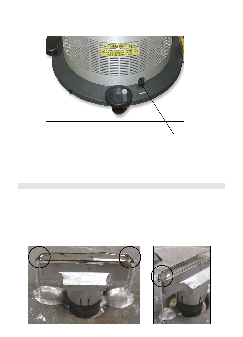
X-Axis
Carrier Lock
Z-Axis
Adjustment Wheel
11. Remove PCB from carrier arms.
• For System 5.2, unlock X-Axis carrier lock.
12. Turn on machine and let temperature stabilize. Adjust temperature as required.
• For System 5.2 turn on preheater. Adjust temperature as required.
Note
ALWAYS HEAT SOAK FLOW WELLS FOR A MINIMUM OF 15 MINUTES BEFORE FLOWING SOLDER.
13. Set solder flow rate. Starting at zero, set mode switch to continuous.
14. Slowly increase flow rate until solder flows off the edge(s) of the flow well. Flow rate is now set for
that flow well. Different flow rate is required for different size flow wells.
Solder Flow
PCBRM15 & PCBRM System 5.2 User’s Manual
Chapter 4: Processes & Applications
Part No. 4005.00.906 4-20
15. Set mode switch to auto (top) position.
16. Place PCB in carrier arms and lock in place with the board lock knobs.
• For System 5.2, tape a type K thermocouple to the PCB using Kapton tape. Plug thermocouple
into the temperature monitor box as required.
• Set the temperature controller on the temperature alarm box to the desired temperature that the
PCB needs to reach.
• Move PCB into the preheater. When alarm sounds, temperature has been met.
17. Move PCB to flow well location.
Mode Switch/Duration/Footswitch
NOTE
UNTIL DURATION (TIME) OF SOLDER FLOW HAS BEEN ESTABLISHED, SET THE DURATION TO THE
MAXIMUM SETTING AND START AND STOP THE FLOW BY USING THE FOOTSWITCH (MANUAL
MODE).
BY USING A STOP WATCH, THE DURATION CAN BE DETERMINED. THE DURATION SETTING IS A
RELATIVE SCALE AND THEREFORE SETTING THE TIME WILL TAKE A COUPLE OF TRIES.
DURATION SCALE IS APPROXIMATELY 0 TO 60 SECONDS.
ONCE THE DURATION IS SET, LEAVE MODE SWITCH IN AUTO. WHEN PCB IS LOCATED OVER THE
FLOW WELL, PRESS START ON THE FOOTSWITCH.
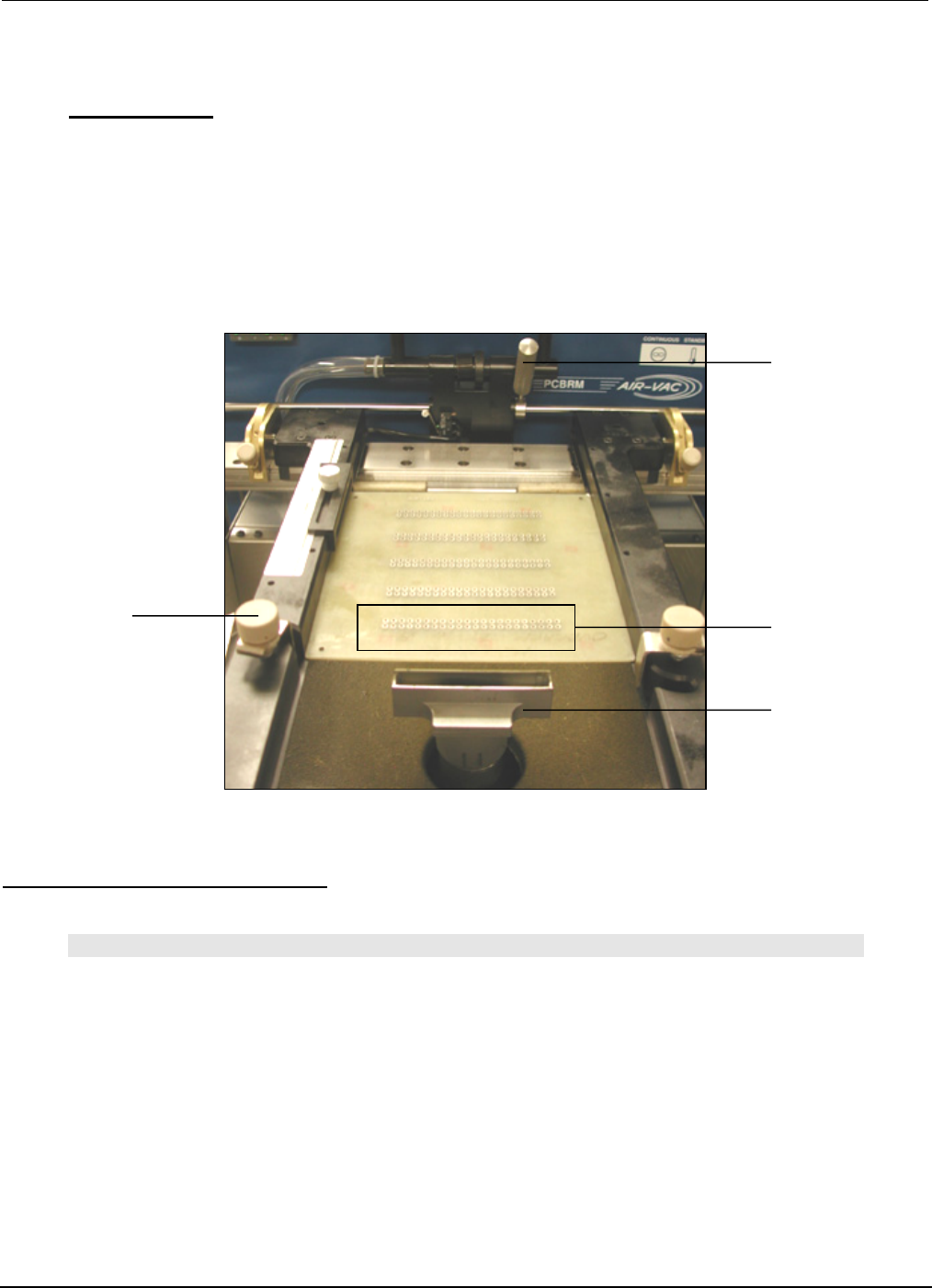
X-Axis
Positioning Knob
Lead
Pattern
Flow
Well
Board
Lock Knobs
PCBRM15 & PCBRM System 5.2 User’s Manual
Chapter 4: Processes & Applications
Part No. 4005.00.906 4-21
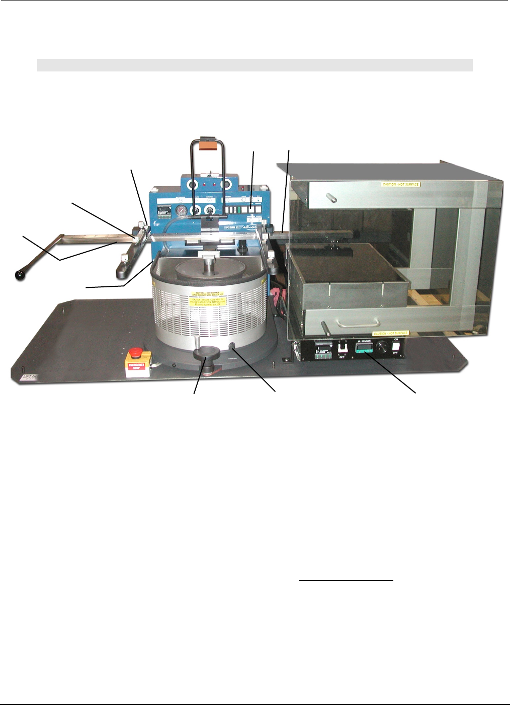
Y-Axis Lock
Z-Axis Lock
Board Lock
X-Axis
Carrier Lock
Z-Axis
Adjustment Wheel
X-Axis Lock
(preheater)
X-Axis Lock
(solder pot)
Board Temperature
Display
Mode Switch
(auto)
4.12 PCBRM System 5.2 - Soldering Sequence: Using Auto Mode for Soldering
Note
SOLDER FLOW AND DURATION MUST BE DETERMINED PRIOR TO THESE STEPS.
1. Install flow well.
2. Load board into carrier. Tighten board locks. If y-axis lock is used, position board to edge and tighten.
3. Slide board into preheater using the carrier handle until x-axis lock (preheat) is reached. Be sure
carrier is in the top position to avoid hitting the flow well. Adjust z-axis adjustment if necessary. Carrier
may be lowered to enhance preheating. Allow board to preheat to desired topside temperature. IR
temperature sensor will monitor and display board temperature.
4. When board has reached desired temperature, alarm will occur. Slide board using the carrier handle
until carrier hits the x-axis lock (solder pot).
5. Turn z-axis adjustment wheel until carrier hits z-axis lock (System 5.2 only).
6. Press left side of footswitch to cycle machine. Solder cycle will occur.
7. Turn z-axis adjustment wheel to top position.
8. Using the carrier handle, slide board to unload/load position. Loosen board locks and remove board.
9. Repeat process.