PCBRM_User_Manual_R9.pdf - 第64页
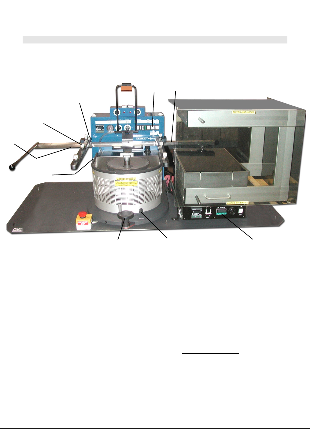
PCBRM15 & PCBRM System 5. 2 User’s Manual Chapter 4: Process es & Appl icati ons Part No. 4005.00.906 4- 22 Y- Axis Lock Preheater Z- Axis Lock Board Lock X- Axis Carrier Lock Z- Axis Adjustment Wheel X- Axis Loc…
PCBRM15 & PCBRM System 5.2 User’s Manual
Chapter 4: Processes & Applications
Part No. 4005.00.906 4-21
Y-Axis Lock
Z-Axis Lock
Board Lock
X-Axis
Carrier Lock
Z-Axis
Adjustment Wheel
X-Axis Lock
(preheater)
X-Axis Lock
(solder pot)
Board Temperature
Display
Mode Switch
(auto)
4.12 PCBRM System 5.2 - Soldering Sequence: Using Auto Mode for Soldering
Note
SOLDER FLOW AND DURATION MUST BE DETERMINED PRIOR TO THESE STEPS.
1. Install flow well.
2. Load board into carrier. Tighten board locks. If y-axis lock is used, position board to edge and tighten.
3. Slide board into preheater using the carrier handle until x-axis lock (preheat) is reached. Be sure
carrier is in the top position to avoid hitting the flow well. Adjust z-axis adjustment if necessary. Carrier
may be lowered to enhance preheating. Allow board to preheat to desired topside temperature. IR
temperature sensor will monitor and display board temperature.
4. When board has reached desired temperature, alarm will occur. Slide board using the carrier handle
until carrier hits the x-axis lock (solder pot).
5. Turn z-axis adjustment wheel until carrier hits z-axis lock (System 5.2 only).
6. Press left side of footswitch to cycle machine. Solder cycle will occur.
7. Turn z-axis adjustment wheel to top position.
8. Using the carrier handle, slide board to unload/load position. Loosen board locks and remove board.
9. Repeat process.
PCBRM15 & PCBRM System 5.2 User’s Manual
Chapter 4: Processes & Applications
Part No. 4005.00.906 4-22
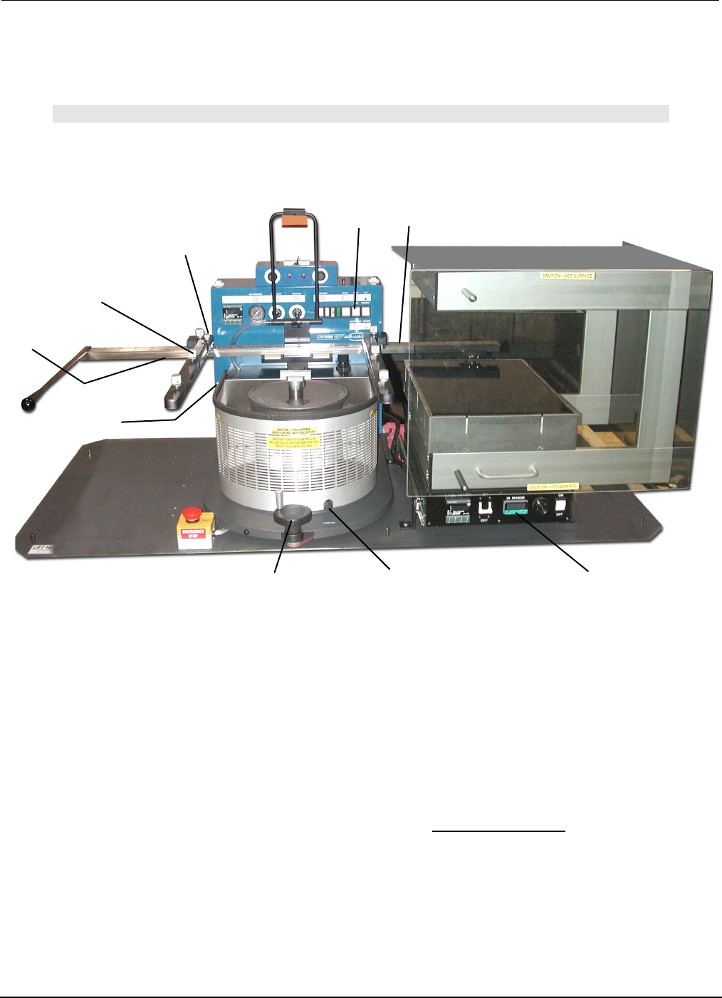
Y-Axis Lock
Preheater
Z-Axis Lock
Board Lock
X-Axis
Carrier Lock
Z-Axis
Adjustment Wheel
X-Axis Lock
(preheater)
Board Temperature
Display
X-Axis Lock
(solder pot)
Mode Switch
(manual)
4.13 PCBRM System 5.2 - Soldering Sequence: Using Manual Mode for
Soldering
Note
SET SOLDER CYCLE DURATION CONTROL TO MAXIMUM SETTING. FLOW MUST BE
DETERMINED PRIOR TO THESE STEPS.
1. Install flow well.
2. Load board into carrier. If y-axis lock is used, position board to edge and tighten. Tighten board locks.
3. Slide board into preheater using the carrier handle until the x-axis lock (preheater) is reached. Adjust
z-axis adjustment when necessary. Be sure carrier is in the top position to avoid hitting flow well.
Carrier may be lowered to enhance preheating. Allow board to preheat to desired topside
temperature. IR sensor will monitor and display board temperature.
4. When board has reached desired temperature (alarm will occur) press footswitch to activate solder
flow. Skim off dross, if necessary.
5. Slide board over solder wave, using the carrier handle—until carrier hits x-axis lock. Turn carrier lock
to set.
6. Turn Z-Axis Adjustment Wheel until carrier hits z-axis lock (System 5.2 only).
7. Allow sufficient time for reflow.
8. Slowly turn Z-Axis Adjustment Wheel moving board upward to allow solder to slowly peel from the
component leads to alleviate bridging.
9. Turn off solder flow by pressing right side of footswitch.
10. Turn Z-Axis Adjustment Wheel to top position. Loosen Carrier Lock. Slide board away from solder
pot using the carrier handle. Remove board.
11. Repeat process.
Process Notes:

PCBRM15 & PCBRM System 5.2 User’s Manual
Chapter 4: Processes & Applications
Part No. 4005.00.906 4-23
• It may be desired to turn on solder flow while board is in the preheat position to allow flow well to
heat soak and dross to be skimmed prior to soldering.
• Reduce bridging by adjusting Ramp Down Flow Rate to zero (0). Or, manually raise board slowly
with Z-Axis Adjustment Wheel while solder is still flowing.
• Flux entire lead area. It may be required to flux topside of board. Allow sufficient temperature to a
be achieved to activate flux.
• Board must be level to solder wave. Fixturing may be required.
• The vertical position of the board is critical for proper soldering results. Allow solder to contact all
leads, but sufficient clearance for solder to flow. Bridging may be reduced by raising carrier position
and allowing solder to wick up the leads.
• Using tacky flux may allow more flux to remain during reflow, reducing bridging.
• Increasing preheat may be required for thermal challenging and lead free assemblies.
• It may be desired to lower the process temperature and increase process time if the board is prone
to delamination and/or discoloring.