PCBRM_User_Manual_R9.pdf - 第55页
PCBRM15 & PCBRM System 5. 2 User’s Manual Chapter 4: Process es & Appl icati ons Part No. 4005.00.906 4- 13 Baffle X- Axis Compliant Arm Lock Knob (right anf left sides) 4.11 Set - Up and Process a PCB (step by s…

PCBRM15 & PCBRM System 5.2 User’s Manual
Chapter 4: Processes & Applications
Part No. 4005.00.906 4-12
4.10 Operator Procedures
4.10.1 Safety Instructions & Recommendations
CAUTION:
OPERATION OF THIS MODULE INVOLVES PUMPING OF MOLTEN SOLDER. ALL NORMAL SAFETY
PRACTICES MUST BE OBSERVED.
Personnel
• Safety glasses should be worn at all times.
• Wear protective gloves when working with solder. Solder could contain tin and lead, which are
hazardous materials.
• Place any waste solder or dross in a heat resistant dross container.
• Always wash hands after working with solder.
• Use caution if wearing loose clothing while operating this machine as loose clothing can fall into
the molten solder. Always secure loose clothing before operating this equipment.
• Never eat, drink, or smoke while working with solder.
• Only trained operators and technicians should work on this equipment.
• Molten solder will cause severe burns. Use extreme caution when operating this equipment. Heat
resistant gloves are recommended particularly when placing and removing Flow Wells, removing
dross, adding solder or removal solder and during maintenance.
• Report any problem to supervisor.
Equipment
• Flow Wells must heat soak on pump housing before attempting to flow solder. Failure to heat
soak Flow Well can cause solder to solidify in the Flow Well openings.
• Flux vapors result from soldering or desoldering. Fresh air must be provided. A venting system or
fume extraction system is recommended.
• Slowly increase flow rate to reach proper flow for the flow well. Do not increase flow rate if solder
solidifies. Allow flow well to heat soak slowly.
• Do not allow solder to flow outside the confines of the solder pot.
• Do not cool flow well with liquid (water). Use only ambient air environment to cool flow well.
• During operation do not allow PCB to seal against flow well.
• Keep all covers on. Do not open machine covers unless you are at the Main Menu Screen for
basic maintenance.
• Keep hands clear of moving parts. Do not reach into the machine during operation.
• Do not override safety interlocks.
• Check area for any loose parts or tools that could cause mechanical interference.
• Do not place anything on the top of the machine.
• In the event of an emergency, press the Red Emergency Stop button located on the front of the
machine. Locate this Emergency Stop button before operating this machine.
• Shut off electrical power and unplug machine when servicing any area of the machine.
• If a malfunction should arise, depress the Emergency Stop button to stop operation.
• The machine should not be operated unless the solder pot cover and flow well are in place.
• Heat resistant gloves should be worn when placing and removing flow wells, removing dross, and
adding or removing solder.
• The machine should not be moved when the solder is molten.
• Refer to material safety data sheet of solder, flux, or any other product used in conjunction with
module. Follow all warning labels and instructions.
PCBRM15 & PCBRM System 5.2 User’s Manual
Chapter 4: Processes & Applications
Part No. 4005.00.906 4-13
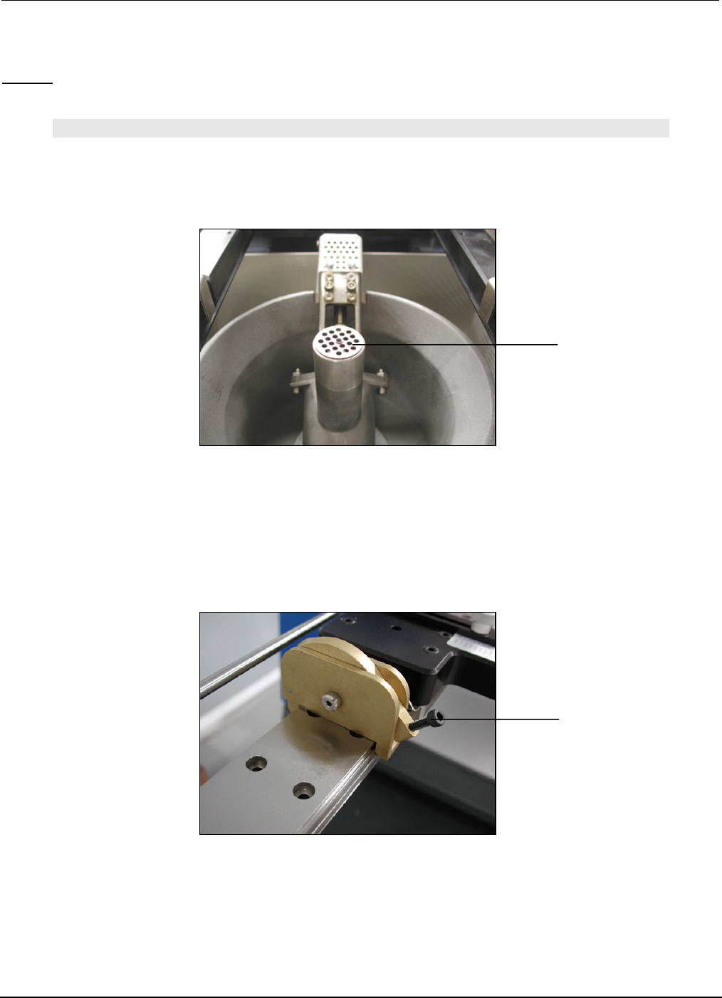
Baffle
X-Axis Compliant Arm
Lock Knob
(right anf left sides)
4.11 Set-Up and Process a PCB (step by step)
Set-up:
NOTE:
BE CERTAIN THAT THE PUMP BAFFLE IS INSTALLED INTO THE PUMP. ADJUST Z-AXIS TO ITS
HIGHEST POSITION. INSTALL FLOW WELL AND CLEANING HOOD IF SO EQUIPPED.
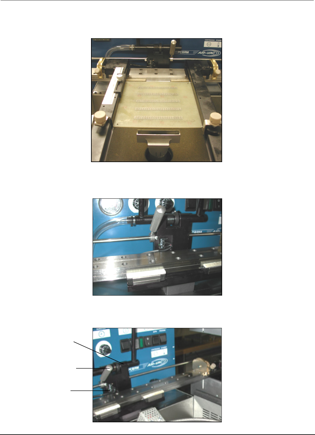
1. Move X-Axis carrier all the way to the left.
2. Move the carrier arms to an approximate position on the X-Axis to hold the board.
3. Lock the left arm to the X-Axis rail.
4. Hold PCB in left arm while moving the right arm to the board. Lock right arm.
PCBRM15 & PCBRM System 5.2 User’s Manual
Chapter 4: Processes & Applications
Part No. 4005.00.906 4-14
Center Bracket
X-Axis Lock (left)
Micro Switch
5. Move X-Axis carrier to the right. Be certain there is enough travel to locate PCB to the flow well.
Adjust arms as required.
5A For System 5.2, be certain there is enough travel to locate the PCB in the preheater. Adjust arms
left or right as required.
5B Move the left X-Axis lock to the right to hard stop the center bracket and micro switch.