PCBRM_User_Manual_R9.pdf - 第57页
PCBRM15 & PCBRM System 5. 2 User’s Manual Chapter 4: Process es & Appl icati ons Part No. 4005.00.906 4- 15 Flow Well Lock Knob PCB NOTE: F OR S YSTEM 5. 2, BE CERTAI N THAT THE PREHEATER IS I N ITS FORW ARD POSI…
PCBRM15 & PCBRM System 5.2 User’s Manual
Chapter 4: Processes & Applications
Part No. 4005.00.906 4-14
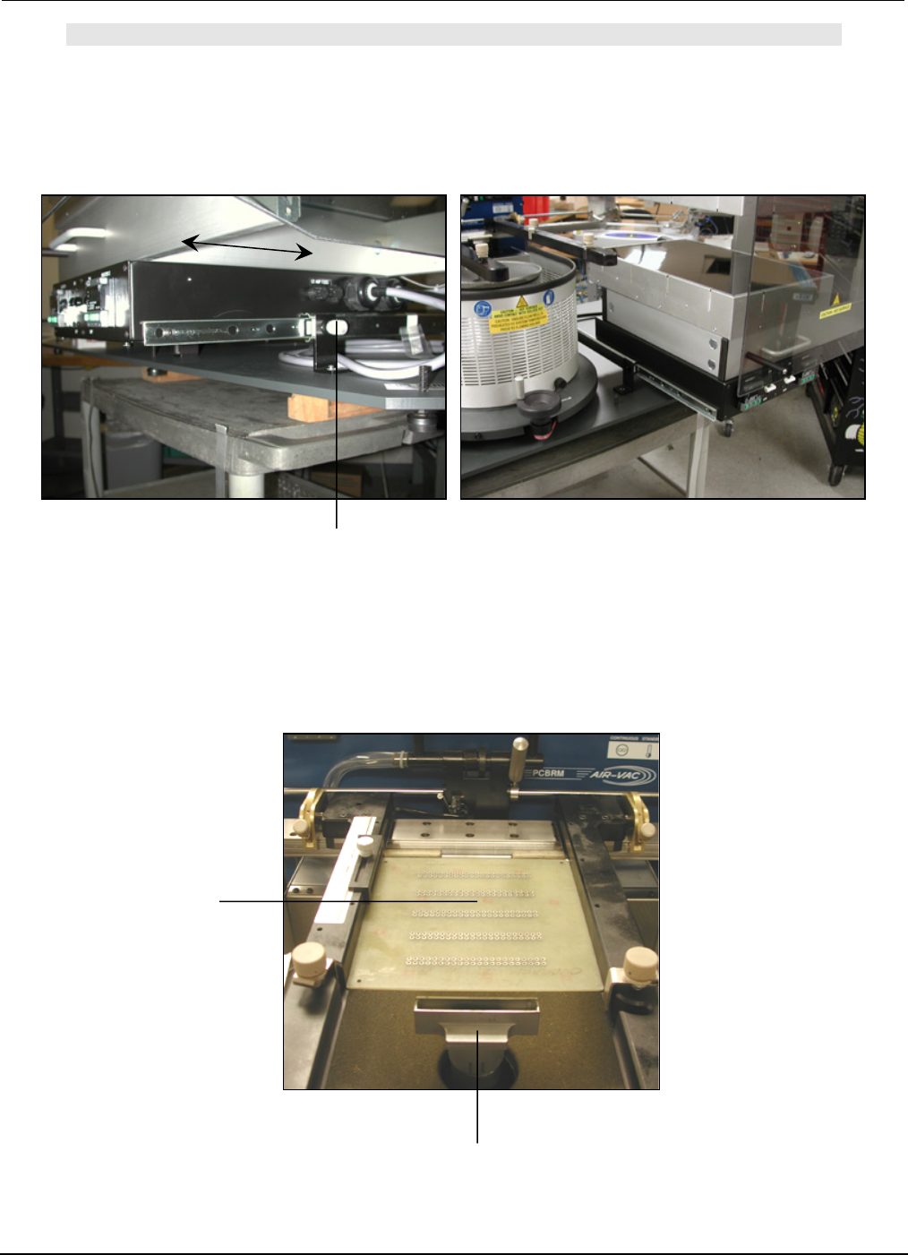
Center Bracket
X-Axis Lock (left)
Micro Switch
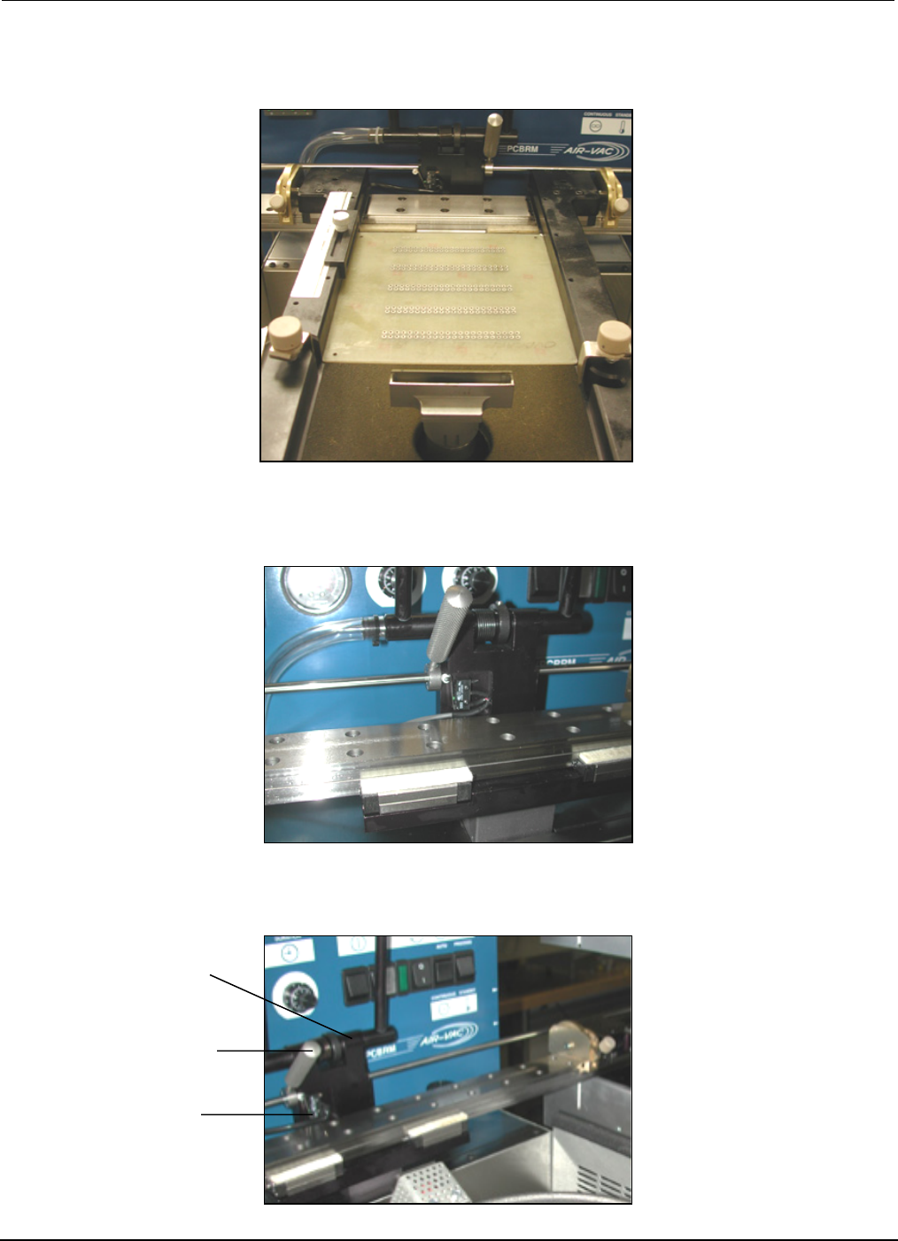
5. Move X-Axis carrier to the right. Be certain there is enough travel to locate PCB to the flow well.
Adjust arms as required.
5A For System 5.2, be certain there is enough travel to locate the PCB in the preheater. Adjust arms
left or right as required.
5B Move the left X-Axis lock to the right to hard stop the center bracket and micro switch.
PCBRM15 & PCBRM System 5.2 User’s Manual
Chapter 4: Processes & Applications
Part No. 4005.00.906 4-15
Flow Well
Lock Knob
PCB
NOTE:
FOR SYSTEM 5.2, BE CERTAIN THAT THE PREHEATER IS IN ITS FORWARD POSITION AND LOCKED
IN POSITION.
6. Move carrier to bring PCB to the flow well location.
PCBRM15 & PCBRM System 5.2 User’s Manual
Chapter 4: Processes & Applications
Part No. 4005.00.906 4-16
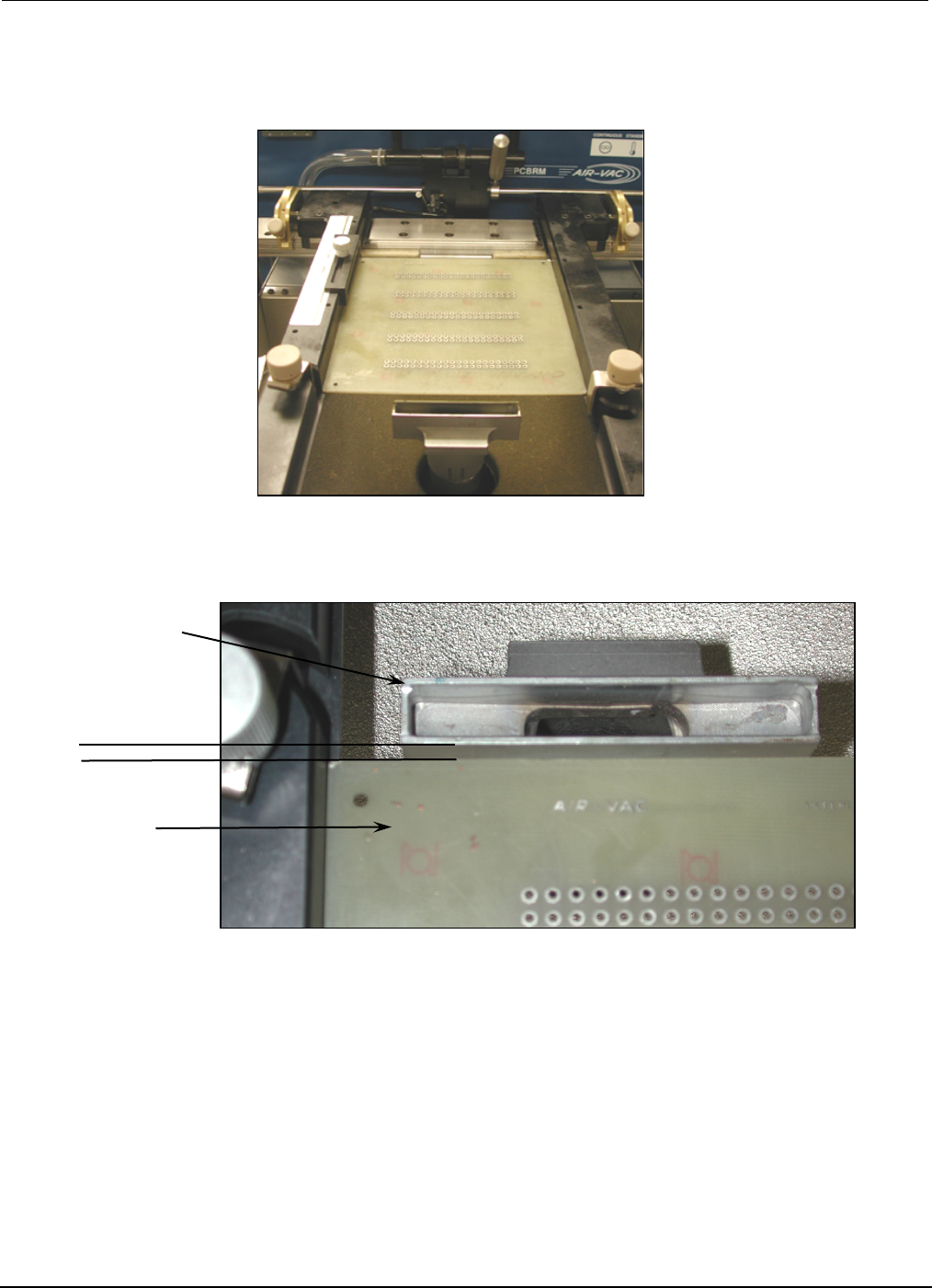
Flow Well
parallel
PCB
7. Lower Z-Axis to bring the PCB to contact the side of the flow well and square flow well to PCB.