PCBRM_User_Manual_R9.pdf - 第85页
Pcbrm15 & PCBRM System 5.2 User’s Manual Chapter 5: Maintenance/Parts Part No. 4005.00.906 5-17 External Heaters maintain uniform heat on large flow wells. Locating Pins accurately position the lead pattern over the …
Pcbrm15 & PCBRM System 5.2 User’s Manual Chapter 5: Maintenance/Parts
Part No. 4005.00.906 5-16
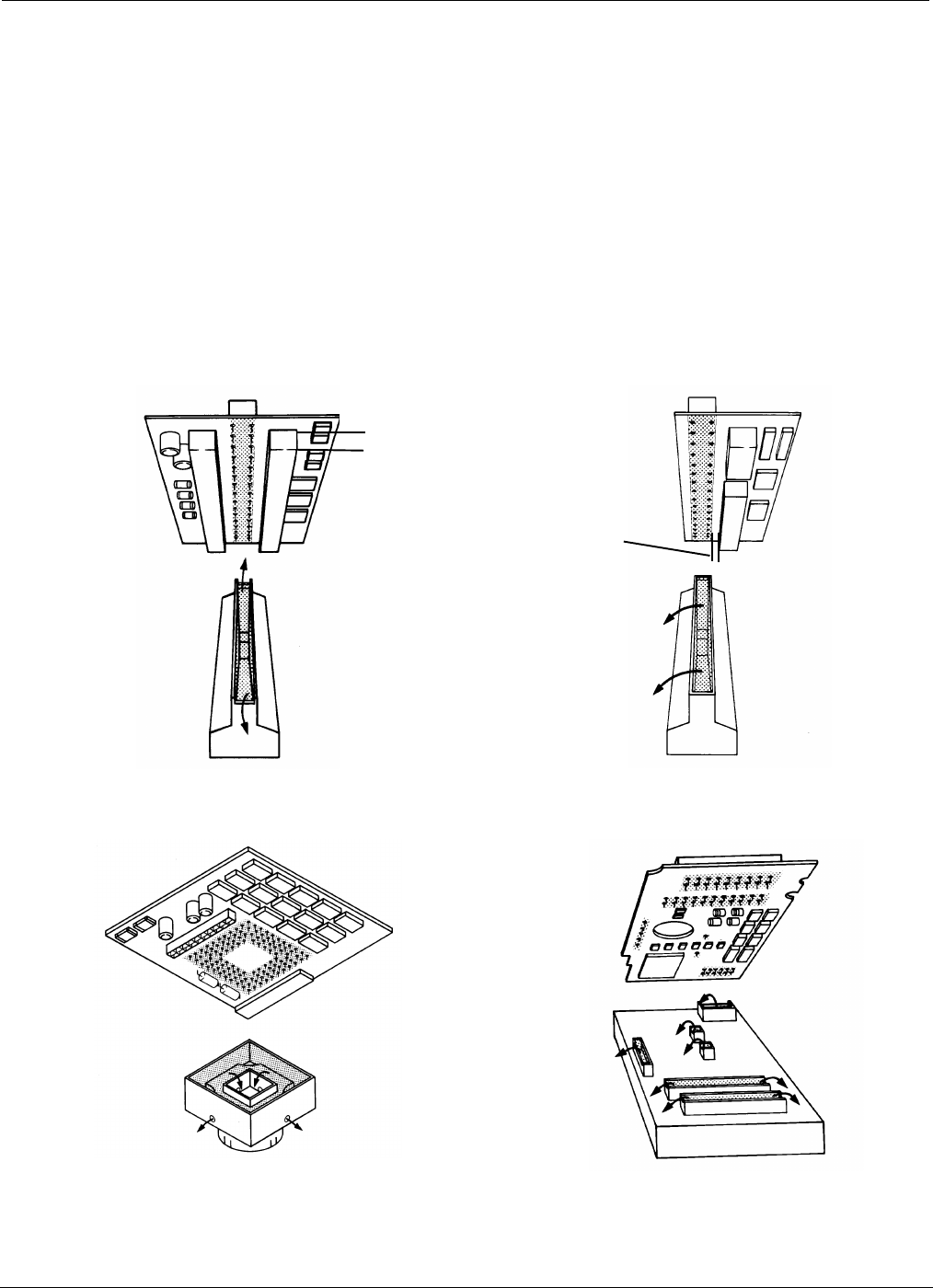
For double-sided boards, solder flow is directed
away from adjacent bottom-side components.
For edge connectors, solder flows away
from the board.
(B)
(A)
The solder flow can be directed inward,
Protecting components near the lead pattern and
limiting heat to adjacent area or components.
The solder flow can be directed to large
select areas for multiple soldering of
components.
5.9 Tooling
5.9.1 Special Soldering/Desoldering Applications
• Special Flow Wells and Cleaning Hoods can be manufactured for specific applications where
issues of clearance, adjacent components and mixed technology boards are concerns.
• Consult Air-Vac for details concerning your specific requirements and the optimum solution.
• A detailed dimensioned customer print and sample of the assembly are critical to design.
Flow Wells determine the size, shape and direction of the solder wave:
• Bottom side critical areas must be addressed. Edge distances (A) and height of bottom side
components (B) must be known.
Pcbrm15 & PCBRM System 5.2 User’s Manual Chapter 5: Maintenance/Parts
Part No. 4005.00.906 5-17
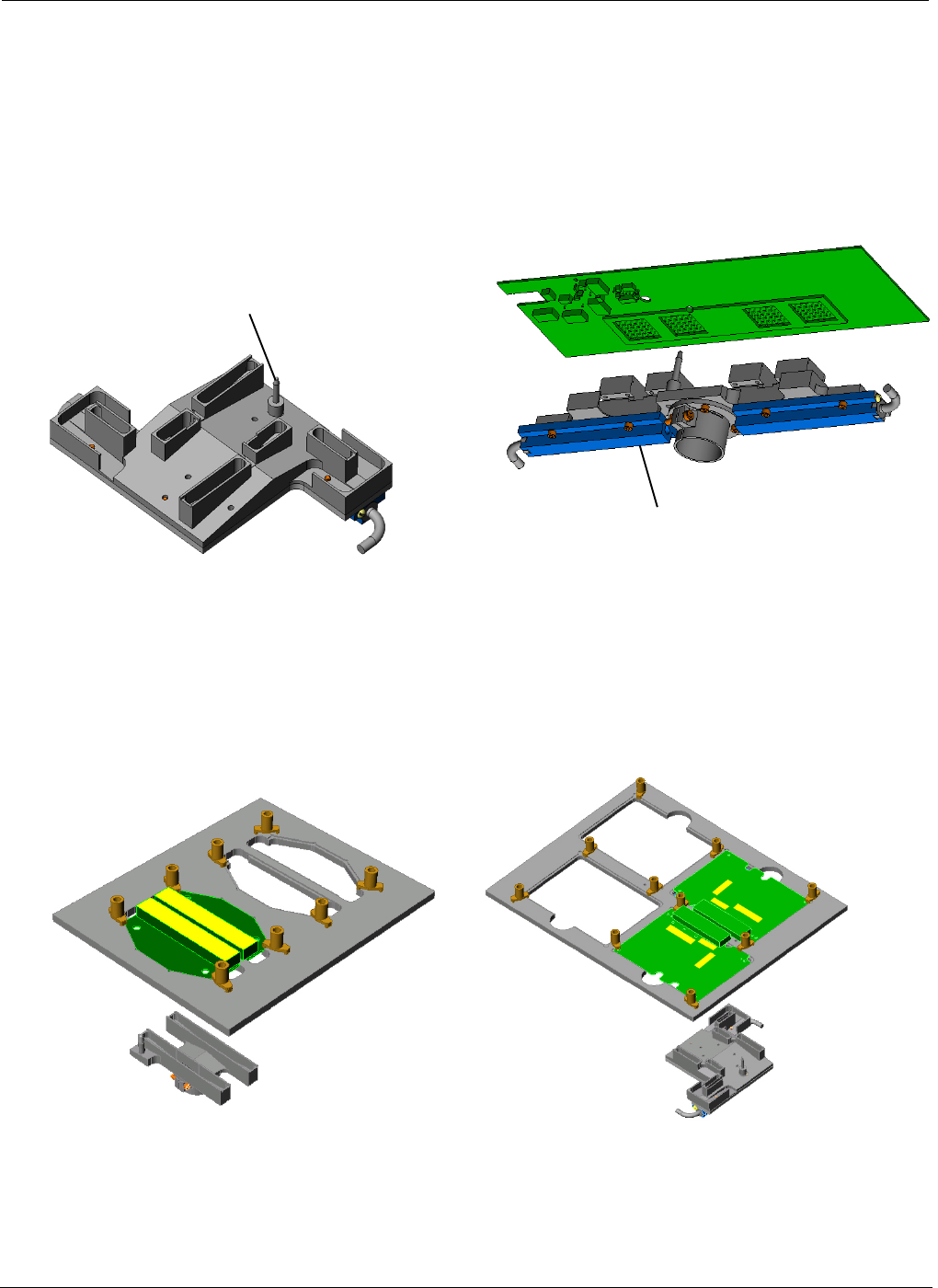
External Heaters maintain
uniform heat on large flow wells.
Locating Pins accurately position the lead
pattern over the solder wave.
Four boards processed.
Two areas processed.
5.9.2 Application Specific Tooling Provides the Most Efficient Process Solution
Send your board to Air-Vac for quick assistance to enhance your process and improve productivity. A
three-dimensional tooling model can be forwarded to you for viewing.
Fixtures allow multiple boards or areas to be soldered in one cycle using the y-axis stop. All boards are preheated
at the same time. Fixtures can also be used to hold irregular shaped boards or support flexible assemblies.
Pcbrm15 & PCBRM System 5.2 User’s Manual Chapter 5: Maintenance/Parts
Part No. 4005.00.906 5-18
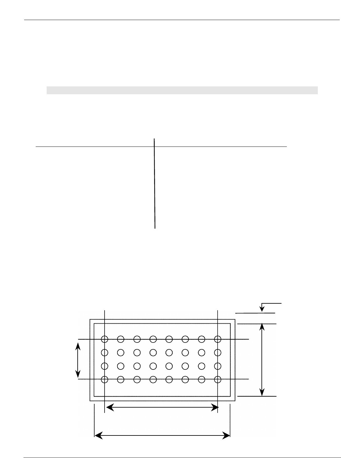
Component
width
Flow Well
width
Component length
Flow Well length
.055 (TYP)
5.9.3 Standard Flow Wells & Air Cleaning Hoods
The flow well must be larger than the component lead pattern to insure that all leads are within the
solder wave. Generally an edge distance of 1/16” is added around the lead pattern and on long
connectors where heat dissipates at the end of the well, an edge distance of 3/16” is recommended.
Note:
NORMALLY CLEANING HOOD DIMENSIONS ARE THE SAME AS FLOW WELL DIMENSIONS. WHERE
DENSITY AND/OR ADJACENT COMPONENT CONFIGURATIONS PRESENT AN INTERFERENCE
PROBLEM, HOODS CAN BE MODIFIED TO MORE CLOSELY CONFORM TO LEAD PATTERNS.
Dimension Flow Well Dimension Flow Well
(W” x L”) Part Number (W” x L”) Part Number
1/4 x 1 1/4 FW8-40 7/8 x 1 5/8 FW28-52
3/8 x 1 3/8 FW12-44 1 x 1 7/16 FW32-46
3/8 x 2 3/16 FW12-70 1 1/8 x 1 1/8 FW36-36
3/8 x 2 3/4 FW12-88 1 1/4 x 1 1/4 FW40-40
3/8 x 3 1/4 FW12-104 1 3/8 x 1 3/8 FW44-44
_ x 29/32 FW16-29 1 _ x 1 _ FW48-48
_ x 1 FW16-32 1 3/4 x 1 3/4 FW56-56
3/4 x 1 5/16 FW24-42 2 x 2 FW64-64
3/4 x 1 _ FW24-48 1/4 x 4 FW8-128
3/4 x 2 FW24-64 3/8 x 5 FW12-160
3/4 x 2 3/16 FW24-70 _ x 5 FW16-160
3/4 x 2 _ FW24-80
Flow Well Sizing
• The size is basically determined by the component pin centerline distances.
• The contact area must include every lead of the pattern to be contacted by flowing solder. The
length and width dimensions must provide generous heat contact and ease for operator
component positioning.