PCBRM_User_Manual_R9.pdf - 第58页
PCBRM15 & PCBRM System 5. 2 User’s Manual Chapter 4: Process es & Appl icati ons Part No. 4005.00.906 4- 16 Flow Well parallel PCB 7. Lower Z - Axis to bring the PCB to contact the side of the flow well and squa …
PCBRM15 & PCBRM System 5.2 User’s Manual
Chapter 4: Processes & Applications
Part No. 4005.00.906 4-15
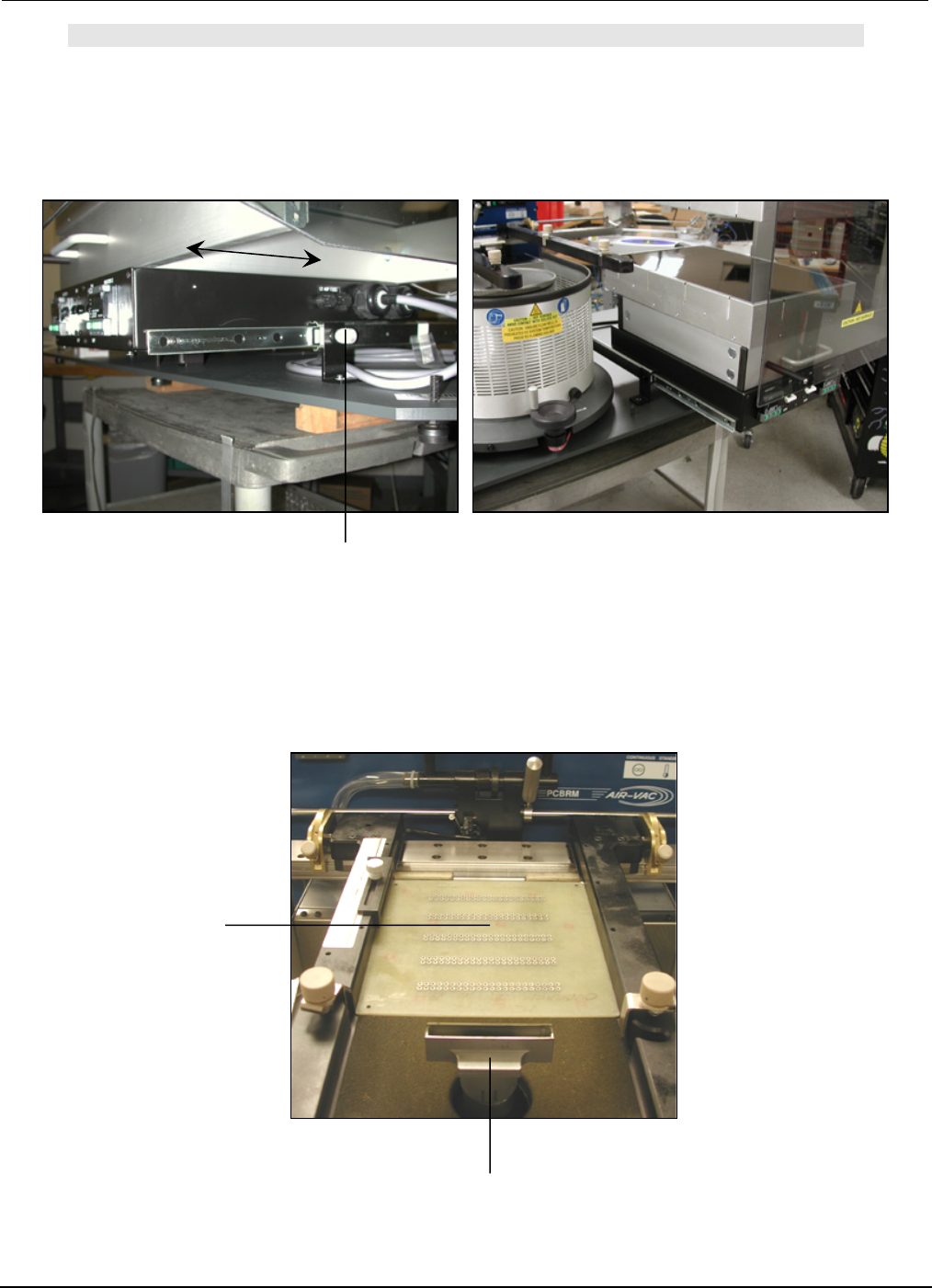
Flow Well
Lock Knob
PCB
NOTE:
FOR SYSTEM 5.2, BE CERTAIN THAT THE PREHEATER IS IN ITS FORWARD POSITION AND LOCKED
IN POSITION.
6. Move carrier to bring PCB to the flow well location.
PCBRM15 & PCBRM System 5.2 User’s Manual
Chapter 4: Processes & Applications
Part No. 4005.00.906 4-16
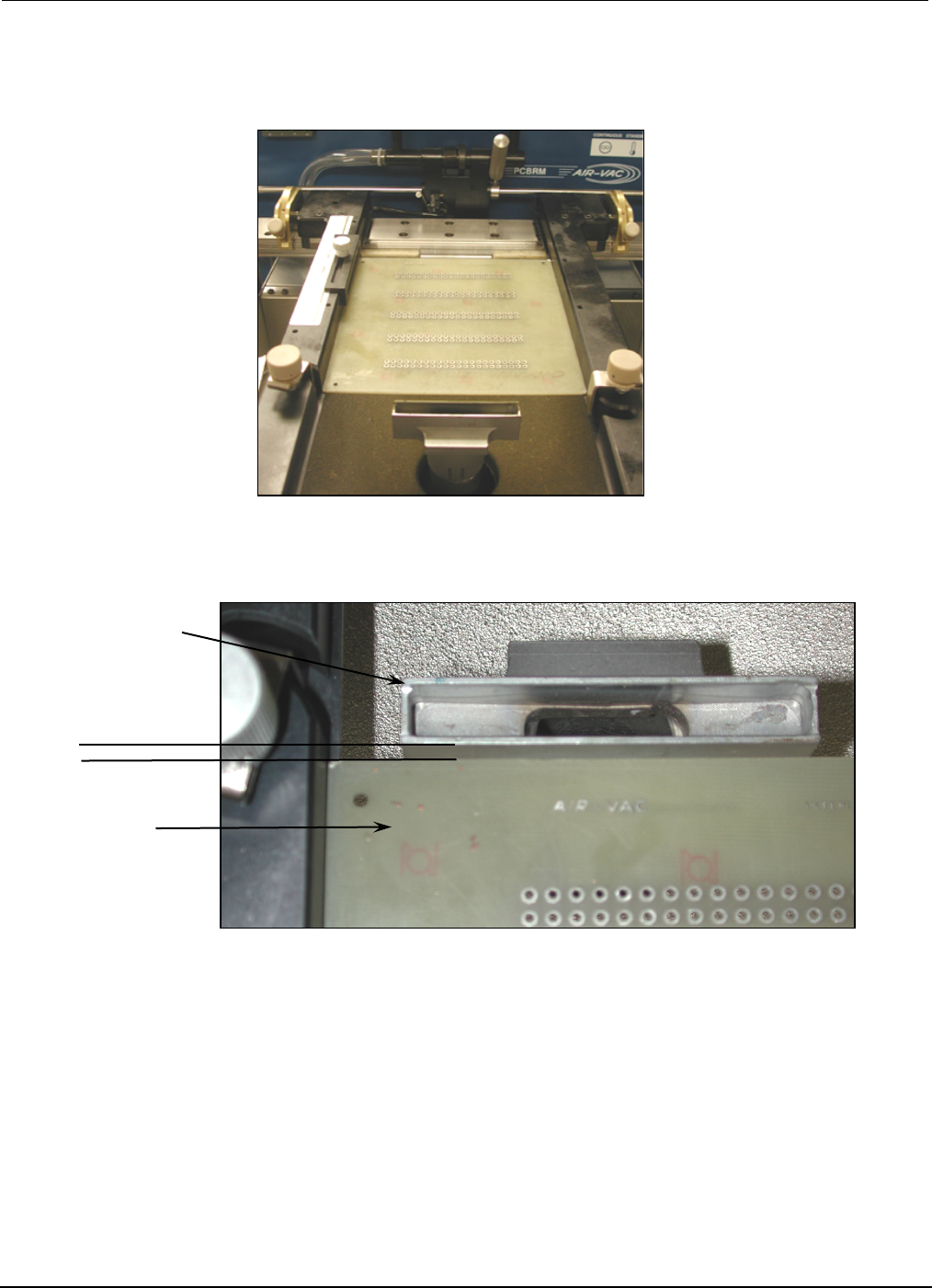
Flow Well
parallel
PCB
7. Lower Z-Axis to bring the PCB to contact the side of the flow well and square flow well to PCB.
PCBRM15 & PCBRM System 5.2 User’s Manual
Chapter 4: Processes & Applications
Part No. 4005.00.906 4-17
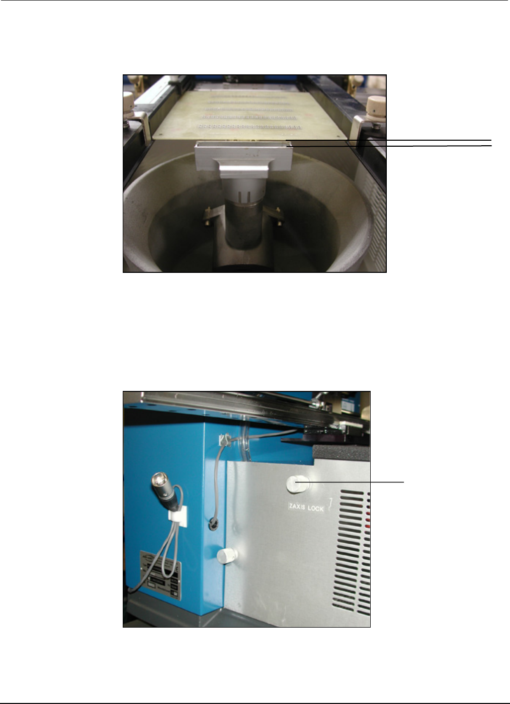
Z-Axis
Positioning Knob
8. Raise Z-Axis using Z-Axis height adjustment wheel and adjust PCB to a height of 1/16” above the
flow well.
• For System 5.2, loosen Z-Axis lock knob and then tighten. The Z-Axis height is now set for
repetitive applications.
1/16”