PCBRM_User_Manual_R9.pdf - 第38页
PCBRM15 & PCBRM System 5. 2 User’s Manual Chapter 3: Set Up & Inst allati on Part No. 4005.00.906 3- 12 (C) (¼ - 20 x 3/8 screws and washers included) 2 ½” hose • Overhead A rm mounts to bracket (C), which moun t…
PCBRM15 & PCBRM System 5.2 User’s Manual
Chapter 3: Set Up & Installation
Part No. 4005.00.906 3-11
(A)
(B)
(B)
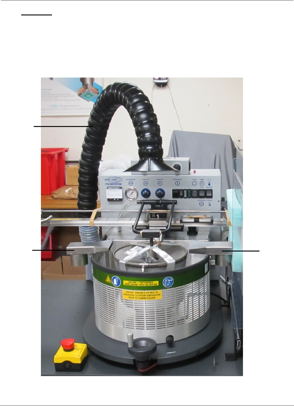
3.7 Optional Fume Extraction Manifold Assembly Installation
• The Optional Fume Extraction Manifold (for PCBRM15 or PCBRM System 5.2) consists of an
Overhead Arm (A), two Exhaust Nozzles (B) and 2” Diameter Hoses which can be attached
to an in-house or separate filtration system.
PCBRM15 & PCBRM System 5.2 User’s Manual
Chapter 3: Set Up & Installation
Part No. 4005.00.906 3-12
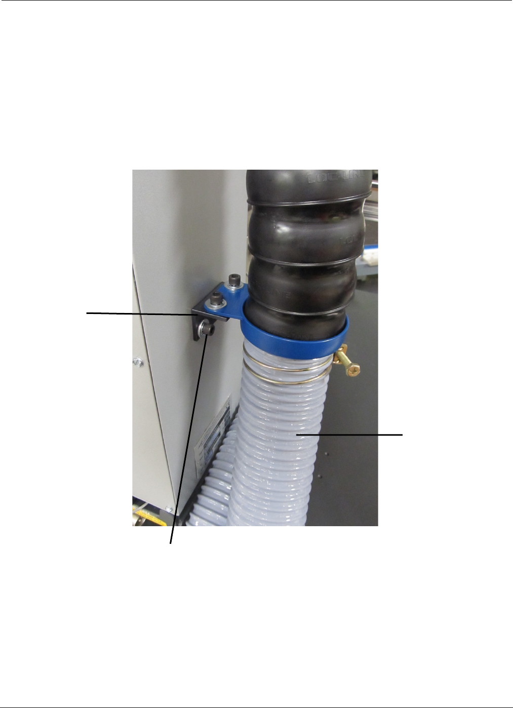
(C)
(¼-20 x 3/8 screws and washers included)
2 ½” hose
• Overhead Arm mounts to bracket (C), which mounts to the left side of the PCBRM (hardware
included).
PCBRM15 & PCBRM System 5.2 User’s Manual
Chapter 3: Set Up & Installation
Part No. 4005.00.906 3-13
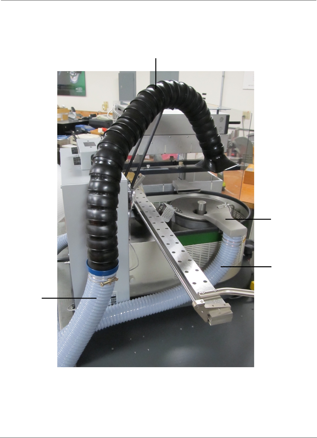
(A)
2” hose
(B)
2 ½” hose