PCBRM_User_Manual_R9.pdf - 第74页
Pcbrm15 & PCBRM System 5.2 User’s Manual Chapter 5: Maintenance/Parts Part No. 4005.00.906 5- 6 Item D escription Qty. Part# (PCBRM15) - Pump Assembly-PCBRM15 1 2004.01.044 A Pump Bracket 1 2004.01.102 (gray iron) B …

Pcbrm15 & PCBRM System 5.2 User’s Manual Chapter 5: Maintenance/Parts
Part No. 4005.00.906 5-5
5.3 Pump Disassembly & Cleaning
CAUTION
SOLDER WILL BE HOT
7. Remove Pump Baffle (P) using needle nose pliers while pump is in the pot with solder.
8. Remove solder from pot using ladle supplied with unit.
Note
ALLOW MACHINE TO COOL BEFORE REMOVING PUMP FROM POT.
9. Remove two screws holding pulley guard to pump.
10. Remove two screws holding pump to pot.
11. Remove two screws holding pump housing (B) to pump bracket (A) and remove housing (B).
Note
DO NOT LOOSEN OR REMOVE THE FOUR LEVELING NUTS (L) AND SET SCREWS (M) OR THE
PUMP WILL NEED TO BE RE-LEVELED UPON INSTALLATION.
12. Loosen the two set screws on the pump pulley (G).
13. Remove the two bearing retaining screws (H) and washer (I).
14. Slide the pump shaft (D) with impeller (C) out of the pump bracket (A). Pump sleeve (N) will
drop away at this point.
15. Remove pump bearings (E), spacer (F) and pulley (G) from pump bracket (A).
Note
INSPECT BEARINGS FOR SMOOTH MOVEMENT. REPLACE IF NECESSARY.
16. Remove pump shaft (D) from impeller (C) and discard.
17. Remove pump sleeve insert (R) and discard.
18. Clean all parts of solder and dirt using a wire brush or a tool to scrape solder from pieces.
19. Re-assemble pump as shown in drawing as follows:
• Insert lower bearing into pump bracket.
• Turn bracket upside down and insert pulley (hub side) into upper bearing hole.
• Place spacer on top of pulley.
• Insert shaft into bracket, through pump sleeve, bearing spacer and pulley.
• Turn bracket over and insert upper bearing.
• Install bearing retaining screws (H) and (I).
• Tighten pulley set screws.
• Install impeller onto shaft – before tightening the set screw be certain the play from the
shaft and bearings will not cause impeller to hit pump bracket face. Allow for this
clearance before tightening set screw.
• Spin shaft with fingers and check for any interference. Correct as required.
• Install pump housing (B) to bracket (A). Be certain the index marks are aligned exactly
before tightening. If they are not, the pump will not be level.
• Spin shaft with fingers and check for any interference between impeller and housing.
20. Pump is now ready for installation back into pot. Use anti-seize on the mounting screws when
installing. Alternate tightening screws until snug. DO NOT OVERTIGHTEN. Over-tightening
could cause pump to become un-level.
21. Check level of pump to carrier arms. Re-level if required.
Pcbrm15 & PCBRM System 5.2 User’s Manual Chapter 5: Maintenance/Parts
Part No. 4005.00.906 5-6
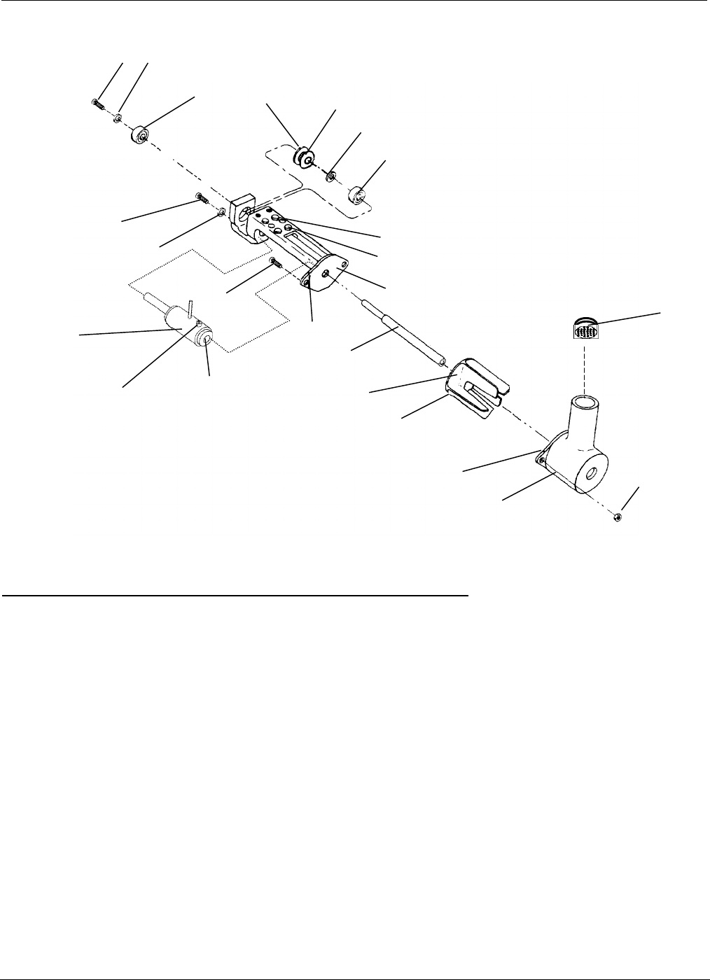
Item Description Qty. Part# (PCBRM15)
- Pump Assembly-PCBRM15 1 2004.01.044
A Pump Bracket 1 2004.01.102 (gray iron)
B Pump Housing 1 2004.01.101 (gray iron)
C Pump Impeller 1 2004.01.100 (gray iron)
D Shaft 1 2004.01.103 (titanium)
E Bearing 2 9001.09.020
F Spacer 1 12464
G Pulley 1 12453
H Screw, 6-32 x 1/4 Button Hd 2 60A
I Washer, #6 SAE 2 9A
J Screw, 10-32 x 5/8 2 9000.00.000 (titanium)
K Nut, 10-32 2 9000.06.002 (titanium)
L Nut, 6-32 x 4 8B
M Set Screw, 6-32 x 5/16 4 11A
N Pump Sleeve Assembly 1 2004.01.041 (titanium)
O Set Screw, 10-32 x 3/8 1 9000.10.249 (titanium)
P Baffle Assembly 1 2004.01.043 (titanium)
Q Pump Mounting screws (10-32 x _) 2 23A
R Pump Insert 1 12418
H
I
E
G
F
E
M
L
A
H
I
J
N
Index Mark
D
C
B
K
upper
HUB
This side
Index Mark
O
P
.
NOTE 1:
When cleaning of pump is required, the pump shaft (D) and the
pump sleeve insert (R) need to be replaced.
R
See note 1
See note 1
9000.02.000
Pcbrm15 & PCBRM System 5.2 User’s Manual Chapter 5: Maintenance/Parts
Part No. 4005.00.906 5-7
5.3.1 Replacement of Pump Bearings:
• Follow all the steps outlined in Pump Disassembly.
• After Impeller and Shaft Assembly are removed, the Impeller Pulley, Bearing Spacer, and
Lower Bearing can be removed.
• Remove Bearing Retainer Hex Screw and Washer, allowing removal of Upper Bearing.
• Use graphite lubricant on screws.
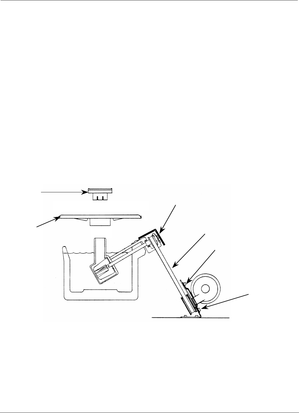
5.3.2 Replacement of Drive Belt (A):
• Disconnect electrical power.
• Remove Rear Cover Screws (4).
• Remove Flow Well (B) & Pot Cover (C).
• Remove Belt Guard Hex Screws (2) and Belt Guard (D).
• Loosen Screws (4) holding Motor (E). Slide motor as high as possible.
• Remove Drive Belt (A).
• Replace Drive Belt and reassemble.
(D)
(A)
(E)
(B)
(C)
(E)