PCBRM_User_Manual_R9.pdf - 第77页
Pcbrm15 & PCBRM System 5.2 User’s Manual Chapter 5: Maintenance/Parts Part No. 4005.00.906 5- 9 • Locate the level in the carrier arm as if it were a PCB. Note the position of the bubble. Place the level on the pump …
Pcbrm15 & PCBRM System 5.2 User’s Manual Chapter 5: Maintenance/Parts
Part No. 4005.00.906 5-8
5.4 Pump Leveling
Carrier Arms Parallel Solder Pump:
Tools Needed:
− 1/16” Allen wrench,
− 5/16” Cresent wrench,
− Bubble level
Steps:
• Mount the pump onto the solder pot and snug the mounting screws. DO NOT OVER TIGHTEN.
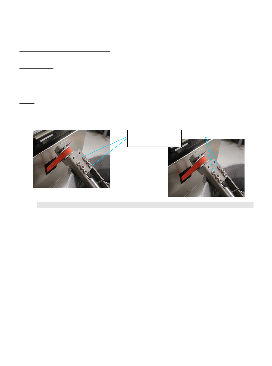
• Bring to bear the (4) leveling screws leaving the lock nuts loose.
Note:
WHEN ADJUSTING THE PUMP, THE TWO MOUNTING SCREWS NEED TO BE LOOSENED PRIOR TO
MAKING ADJUSTMENTS TO ANY OF THE LEVELING SCREWS. THEN, SNUG BACK DOWN TO READ
THE LEVEL. TWO LEVELING SCREWS NEED TO BE ADJUSTED IN ANY ONE ADJUSTMENT.
EXAMPLE – WHEN PARALLELING THE PUMP TO THE CARRIER ARMS, EITHER THE RIGHT TWO
SCREWS WILL BE ADJUSTED TOGETHER, OR THE LEFT TWO SCREWS TOGETHER FOR
EAST/WEST ADJUSTMENT. AND THE BOTTOM TWO SCREWS WILL BE ADJUSTED
TOGETHER OR THE TOP TWO SCREWS FOR NORTH/SOUTH ADJUSTMENT IT IS ALSO
VERY CRITICAL TO ADJUST BOTH SCREWS EXACTLY THE SAME AMOUNT.
Right two leveling
screws and lock nuts
Top two leveling screws and
lock nuts
Pcbrm15 & PCBRM System 5.2 User’s Manual Chapter 5: Maintenance/Parts
Part No. 4005.00.906 5-9
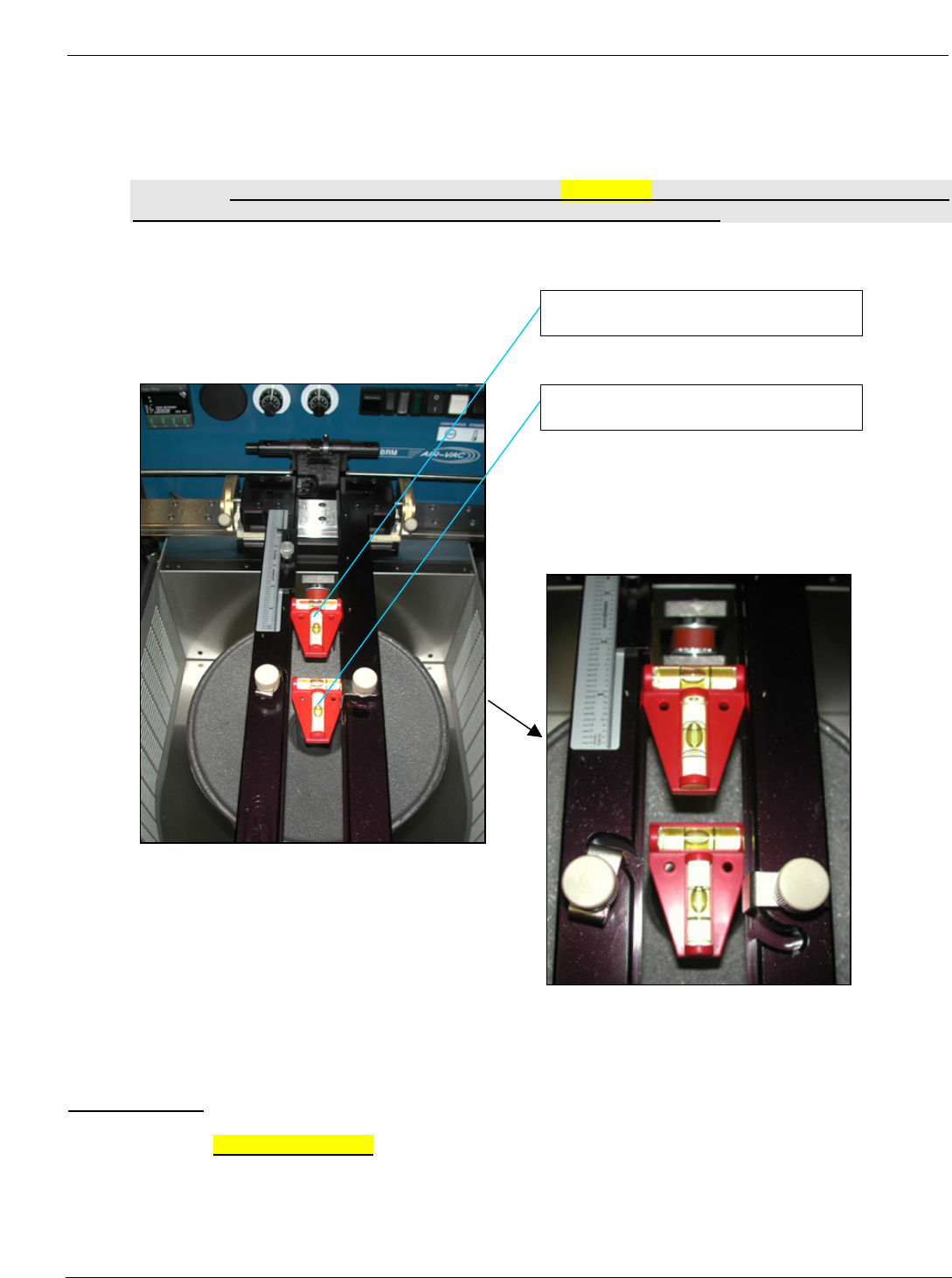
• Locate the level in the carrier arm as if it were a PCB. Note the position of the bubble. Place the level
on the pump housing stack the same way. Note the difference between the two bubbles. Determine
which two leveling screws will need to be adjusted and by how much.
Note: THE PUMP HOUSING STACK MUST BE PARALLEL TO THE CARRIER ARMS. THEY DO
NOT NEED TO BE LEVEL. LEVELING THE MACHINE IS THE NEXT STEP
• Re-check the level of the pump and lock down the (4) lock nuts. DO NOT OVER TIGHTEN.
Machine Level:
• Next level the machine , place level on the solder pump and level the machine on a
workbench. Bring the bubble dead center in both x and y positions by using the machine
legs. Once level has been achieved, lock legs in place with jam nut.
Level located in the carrier arms
Level located on the solder pump
Pcbrm15 & PCBRM System 5.2 User’s Manual Chapter 5: Maintenance/Parts
Part No. 4005.00.906 5-10
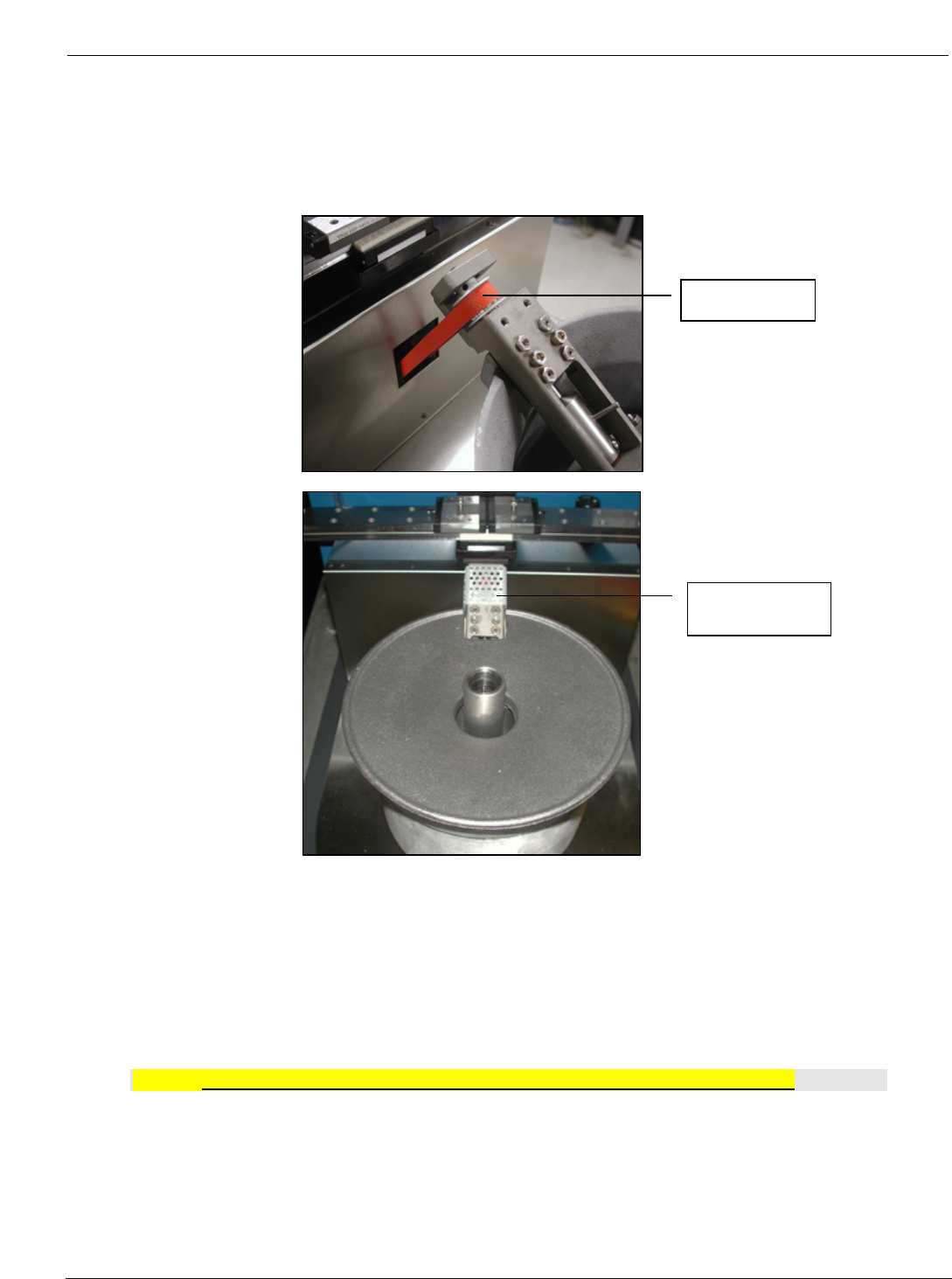
• Install motor belt to pump and motor. Apply downward pressure on motor to achieve belt. Tension
and tighten motor screws.
• Attach pulley guard (2) 1/4 hex head screws.
• Install pot heat shield.
• Install rear door.
• Turn machine on and let it heat up.
Note: Do not run pump without solder. Damage to the pump sleeve will occur!
• Once machine comes up to temperature, load lead free solder (approx. 35 lbs), _” from top of pot.
• Once pot is filled with solder, place pot cover on pot.
Motor belt
Pulley guard