PCBRM_User_Manual_R9.pdf - 第31页
PCBRM15 & PCBRM System 5.2 User’s Manual Chapter 3: Set Up & Installation Part No. 4005.00.906 3-5 3. Place the board to be used in the process in to the carrier arms. Align the site to be processed on the board …
PCBRM15 & PCBRM System 5.2 User’s Manual Chapter 3: Set Up & Installation
Part No. 4005.00.906 3-4
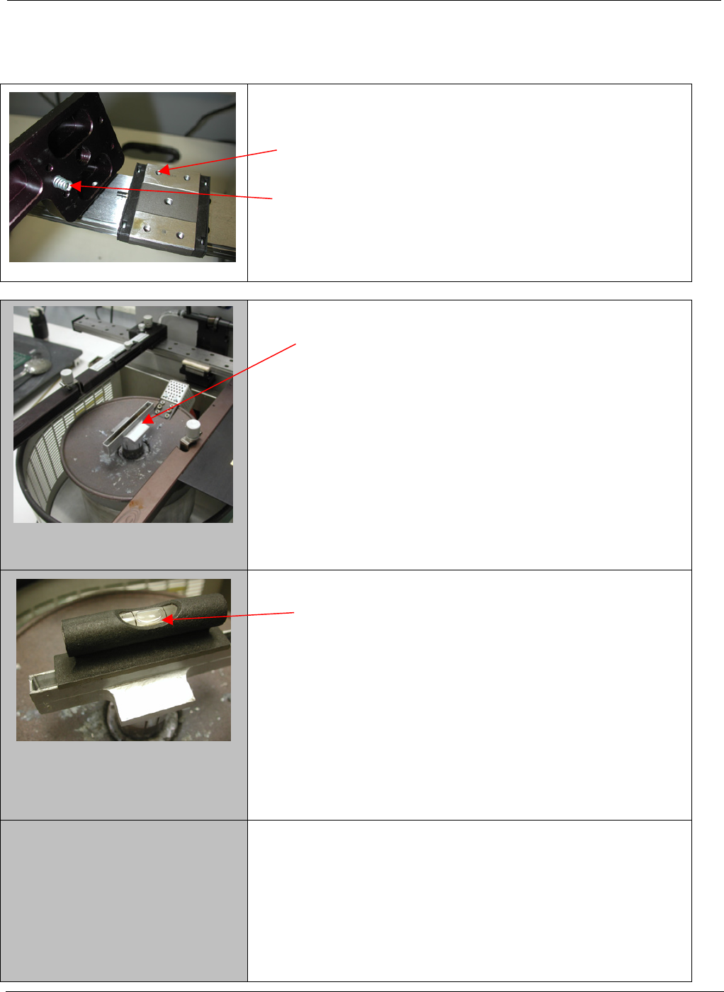
3.2 PCBRM15 – Carrier Arms Installation
• Install right and left carrier arms to the bearing block
using the M4 screws supplied.
• When installing the arms, please note that the spring
must be installed as shown.
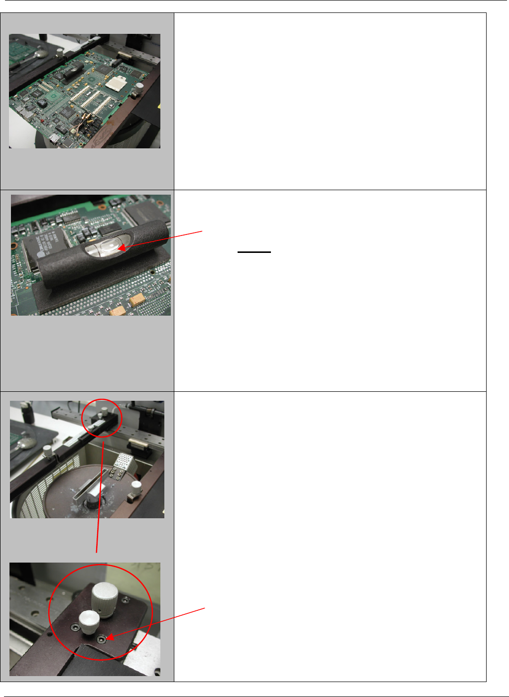
1. Start with a flow well installed on the solder pump.
2. Place a level on the flow well and note level of the
well.
PCBRM15 & PCBRM System 5.2 User’s Manual Chapter 3: Set Up & Installation
Part No. 4005.00.906 3-5
3. Place the board to be used in the process in to the
carrier arms. Align the site to be processed on the
board over the flow well and lock in place.
4. The board now will need to be leveled to match the
flow well. (step 2)
NOTE: The adjustment will be in the Y-axis only
not the X-axis
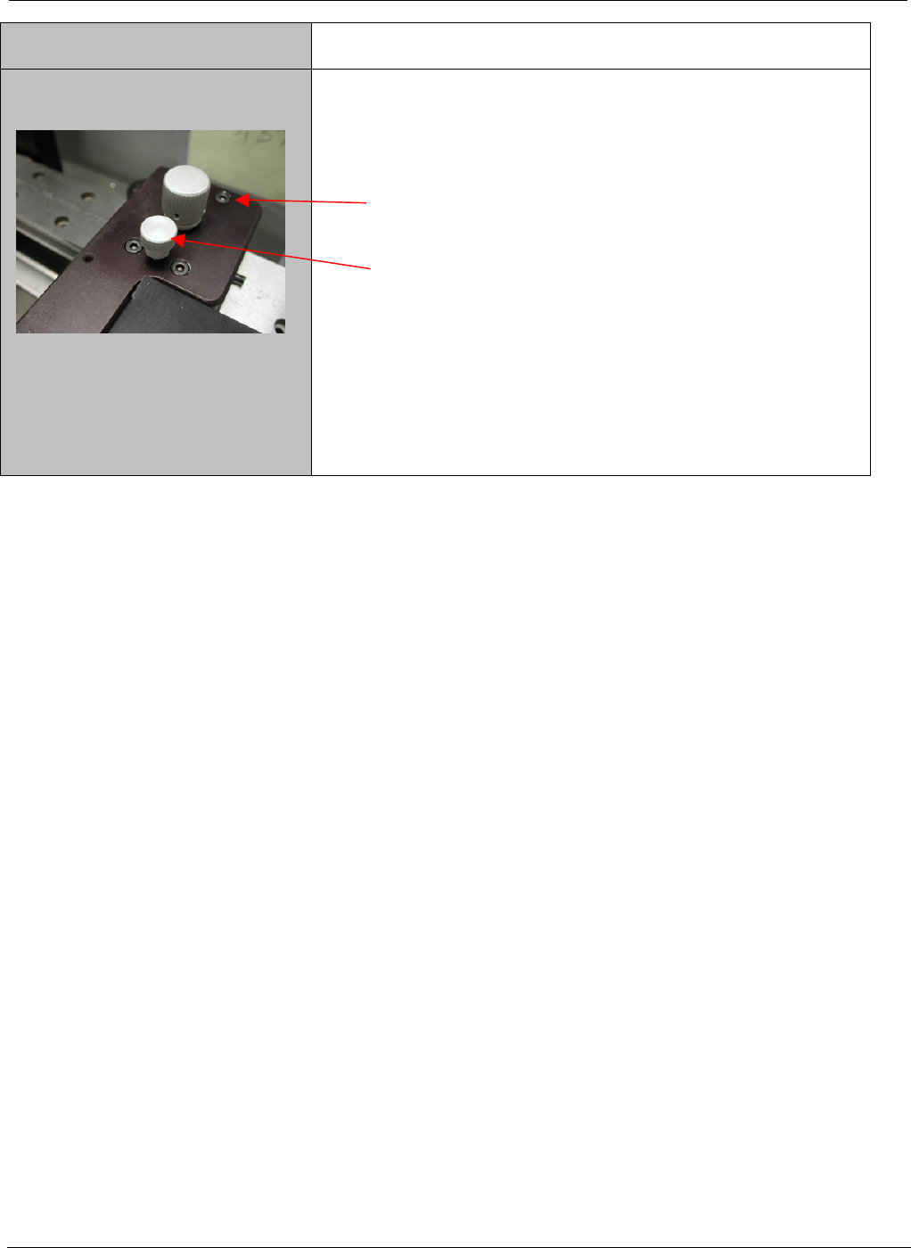
5. To adjust the board to match the flow well, loosen
the two front screws only on each arm two turns.
PCBRM15 & PCBRM System 5.2 User’s Manual Chapter 3: Set Up & Installation
Part No. 4005.00.906 3-6
6. Loosen the rear two screws of each arm _ turn.
7. Turn the adjustment screw clockwise on both arms
equally an 1/8 of a turn at a time until the level is at
the desired place.
8. Once level is achieved, bring the rear two screws
to bare only. Make a final adjustment as required
and bring the front screws to bare. Now snug up all
the screws – Do Not Over tighten.